UML legend
Unified Modeling Language is a standard graphical language for presenting different elements of Software design. The following examples are some of the most common elements of UML.
For more information about formal specifications, see Object Management Group.
UML diagrams consist of the following items:
- Boxes
- Boxes represent classes of objects. Yellow boxes denote core data or assets and are central to the diagram. White boxes denote important information, but are not crucial. The class names appear at the top of the box. Attributes, if shown, appear below the class name. The class name and attributes are separated by a line.
- Lines
- Lines represent possible relationships between objects of two classes. Objects of the class on one end of the line can be "associated" of the class on the other end of the line.
- Filled diamonds
- Filled diamonds on the end of a line indicate containment by value. Objects of the class on the other end of the line are part of one and only one object of the class the diamond touches.
- Hollow diamonds
- Open diamonds on the end of a line indicate containment by reference. Objects at the diamond end of the line can be thought of as grouping objects of the class at the other end of the line.
- Cardinality numbers
- These numbers appear at the end of relationship lines to indicate
a cardinality restriction.
- 1
- One and only one
- 0..1
- Zero or one
- 0..n
- Zero or more
- 1..n
- One or more
If no cardinality restriction is shown, the cardinality is assumed to be 0..n, unless a solid diamond appears on the end of a relationship line. In that case, the cardinality must be 1.
- Plus signs
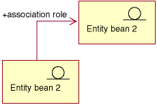
- Plus signs that appear at the end of relationship lines indicate that the object of the class at the end of the line plays a role in the relationship. Text following the plus sign indicates the role of the object in the relationship.
- Arrows
- Arrows at the end of a relationship line indicate the direction of the relationship between two objects is in the direction of the arrow. The absence of any arrows on a relationship line indicates the direction of the relationship between the objects is normally in both directions.
The following diagrams illustrate the preceding concepts:
Example 1

This diagram shows two entity beans with the decoration stereotype symbol that indicates an enterprise bean. There is a unidirectional association from the first bean to the second entity bean. The plus sign is followed by text that describes what role Entity bean 2 plays the association.
Example 2

In this diagram, a StoreEntity has one and only one owner, which is a Member. A Member can own zero or more StoreEntities. The plus sign indicates that the Member plays a role in the relationship. In this case, the Member is the owner of the StoreEntity. The arrow indicates that you can determine the owner of a StoreEntity by asking the StoreEntity for its owner, and not by asking a Member for all of the StoreEntities it owns.
Example 3

In this diagram, an OrderItem is always part of one and only one Order. An Order has zero or more OrderItems.
Example 4

This diagram indicates that a CalculationCode is grouped by zero or one TaxCodeClassifications and a TaxCodeClassification group zero or more CalculationCode.