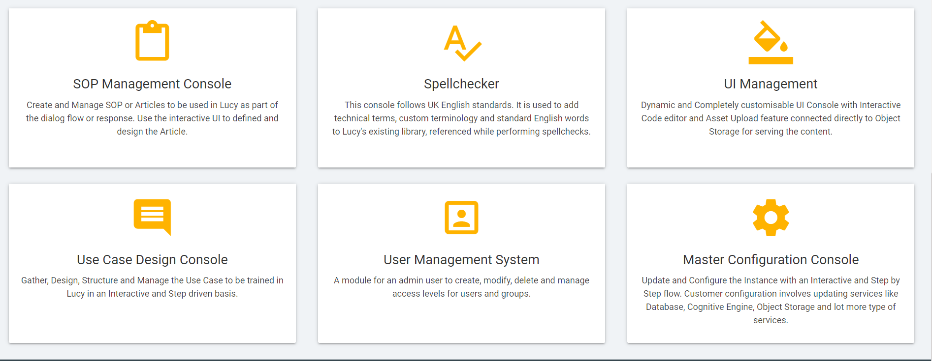
The use case design console (also known as the UCD console) is
the primary area where conversation design is done for a particular
skill or tenant. Users can create new skills, intents, entities and
finally the dialog nodes to handle user utterances and customize
conversational experience.
This console helps to configure the usecases to interact with
the customers in a useful way by addressing their queries and
providing suitable responses.
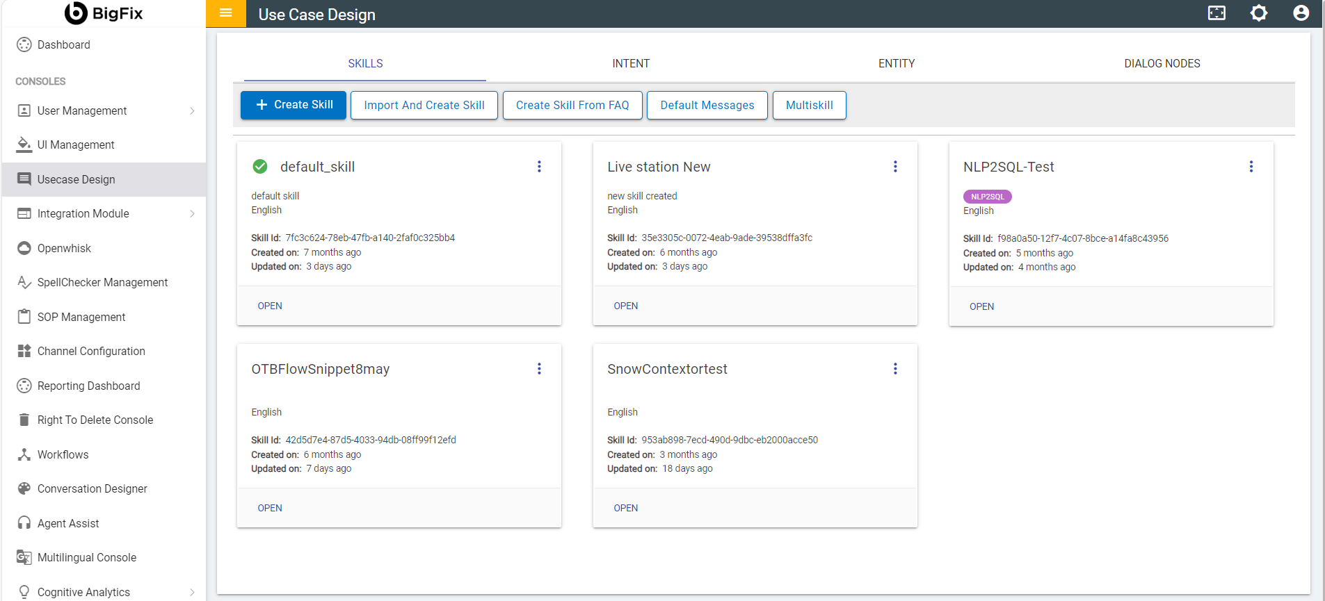
Go to Admin Dashboard Console under BigFix AEX Cognitive
Consoles and click on Usecase Design Console.
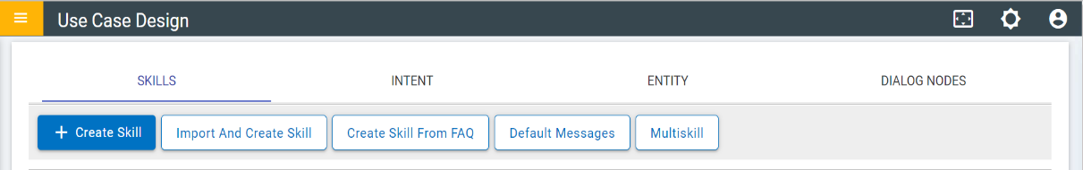
Select SKILLS tab. Two buttons are available
under this tab:
Create Skill
Import and Create Skill
Click on CREATE SKILL button under
SKILLS tab to create a new skill.
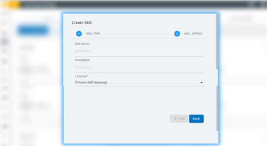
The CREATE SKILL form appears:
Figure 2. Figure 2 - CREATE SKILL
form
The following fields need to be populated:
Skill Name: Enter the name of
the new skill.
Description: Provide brief description about
the skill.
Language: Select the preferred Language from
the drop-down.
Click on Add button.
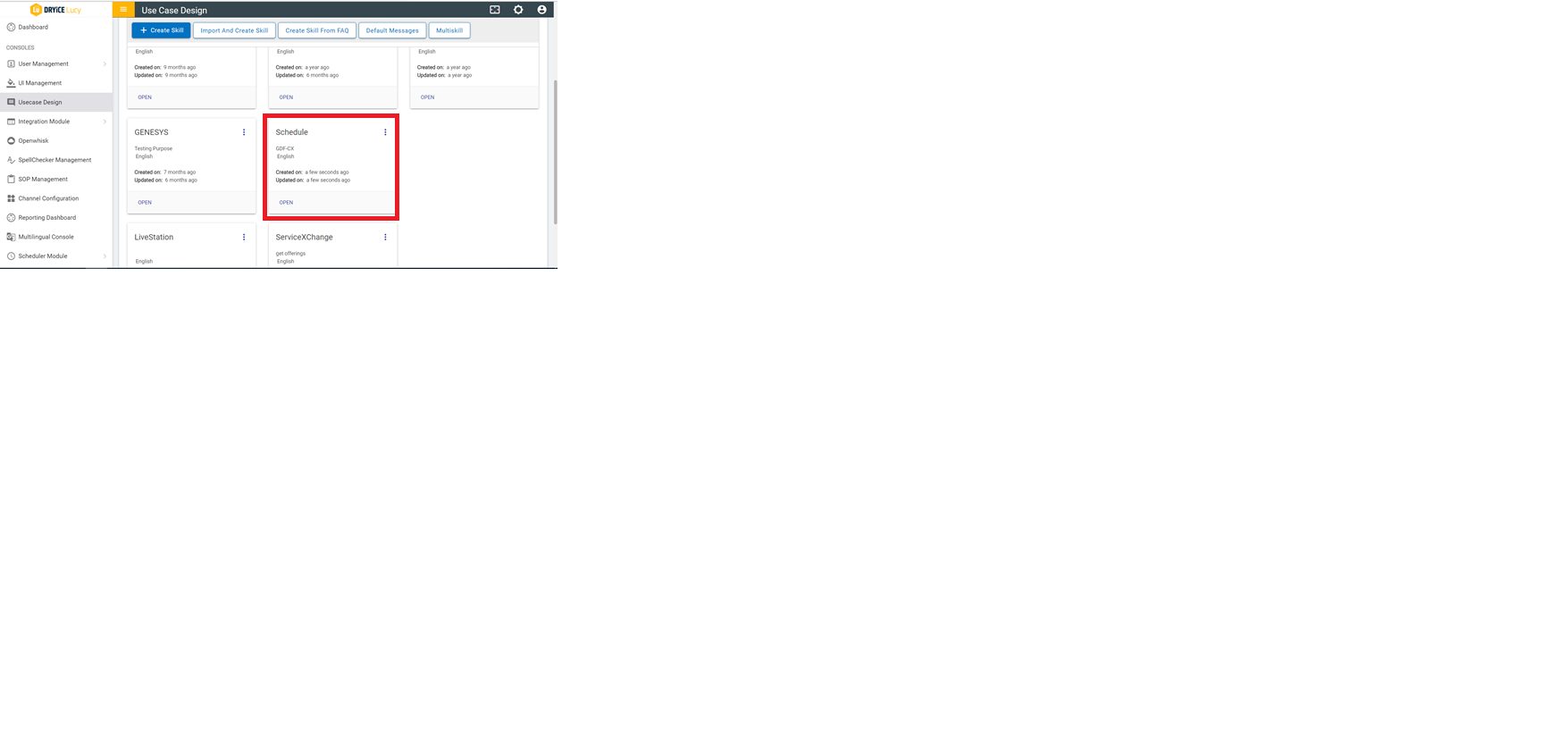
The new skill will be created and will be visible under the
SKILLS tab.
Figure 3. Figure 3 – Usecase
Design Console
Click on OPEN THIS on the newly added
skill.
The following screen appears with new tabs under the newly
added skill:
Figure 4. Figure 4 - Usecase Design
Console
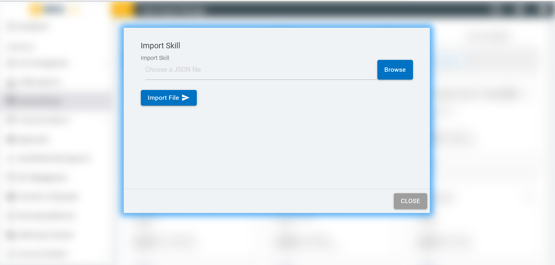
Click on IMPORT AND CREATE SKILL button under
the SKILLS tab to create a new skill with the
existing intents, entities and dialog nodes.
It prompts you to Import the JSON file.
Figure 5. Figure 5 – Import
Skill
Click on
BROWSE button and select a JSON file that you want
to upload.
Click on IMPORT FILE.
Once the file is imported a success message appears and the
imported intents, entities and dialog nodes become visible under
INTENT, ENTITY and
DIALOGNODES tabs
respectively.
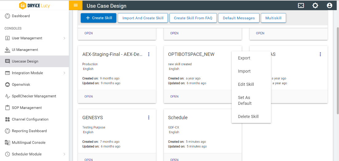
Click on OPEN THIS button present on each
skill to open an existing skill.
To view the entities, intents and dialog nodes associated with
the skill click on ENTITY, INTENT
and DIALOG NODES respectively.
The Kebab menu (the three dots menu) present on each skill
allows you to open a menu with additional options. The following
options are available:
Export: Allows to download the JSON file
associated with a particular skill.
Import: Allows to import the existing intents,
entities, and dialog nodes for a particular skill. Follow the steps
explained above (Step 11
to Step 13) to perform the import action.
MULTISKILL on Usecase design enables switching
between the multiple skills. The console facilitates user to be
able to add skills which he chooses to switch between and choose a
default skill for the conversation. The Multi Skill
Orchestration includes the default method, waterfall
method, broadcast method and the conductor-follower method. In
default method there are option to select the skill while in other
methods the transition between skills would be automated.
Below is an explanation of how each method of skill
orchestration differs and is similar to the others:
Default Model:
This is the already existing (and till now the only) method in
multi skill functionality. Here we get options to select multiple
skills in the use case design console and associate a button name
to it and select one default skill among the selected skill.
In the chat window we get the options to choose from the skill
that we saved in UCD multi skill and further communication
continues with the selected skill.
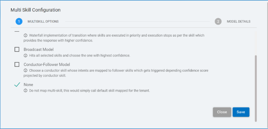
Waterfall Model:
It is a priority-based method i.e., the skill with highest
priority would be checked first. If it provides the correct answer
(doesn’t reaches to the Anything else node) then BigFix AEX
does not go to the subsequent skills.
If execution reaches to the last skill and still reaches
Anything else of the last skill, the message associated with that
node would be returned. On the Use Case Design Console, the user
selects the skills and their priorities.
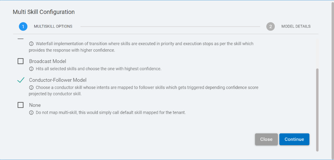
Broadcast Model:
This method is based on the Highest confidence score of skill
i.e., BigFix AEX checks all the skill at once and provides response
from the skill that has the highest confidence score.
In this method, we select a default skill, and that skill
provides us with the welcome message, also in cases where we
don’t get appropriate response, we will have Anything else
node message from this skill.
On Use Case Design Console, the user selects the skills and
chooses one default skill.
Conductor-Follower Model:
In the Conductor-Follower method, there are 2 types of skill
selection,
conductor skill: In this skill, the user adds
1 skill.
follower skill: In this skill, the user has
multiple categories to add.
The conductor skill acts as a default skill and is responsible
for the transition of skill i.e., based on the user’s query,
the conductor skill selects a follower skill for further
communication.
The conductor skill, based on specific conditions, sends the id
of the selected follower skill as part of intent and this id in
turn is used to call the skill for further communication.
Multiskill Configuration – Default Model
Perform the following steps for MULTISKILL configuration using
the Default Model:
Go to the BigFix AEX Tenant and open use case design
Console.
Figure 9. Figure 9 – BigFix AEX
Console
After Opening the use cases design Console, you can find the
Multi skill button. Click Multiskill.
Figure 10. Figure 10 – Use Case
Design Console
In the Usecase Design console the MULTISKILL feature is visible
only if the instance is enabled with the multi skill
configuration.
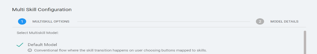
The Multi Skill Configuration page appears.
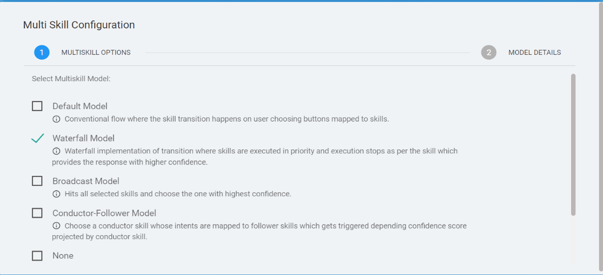
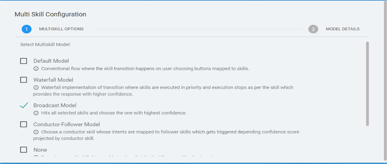
The page lists all the available models. Select the model and the
console displays the corresponding options based on the
selection.
Select the Default Model and click
‘Continue’.
Figure 11. Figure 11 – Multi Skill
Configuration Page
If user selects the None option in the Multi
skill Configuration page, by default, it takes the default model
for the skills to be mapped for the tenant.
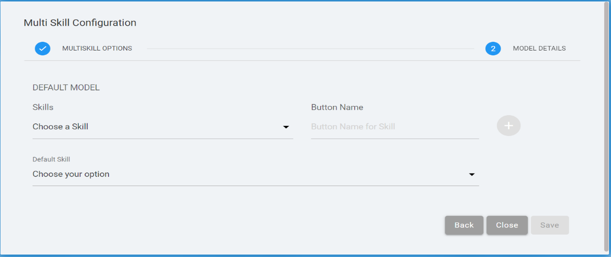
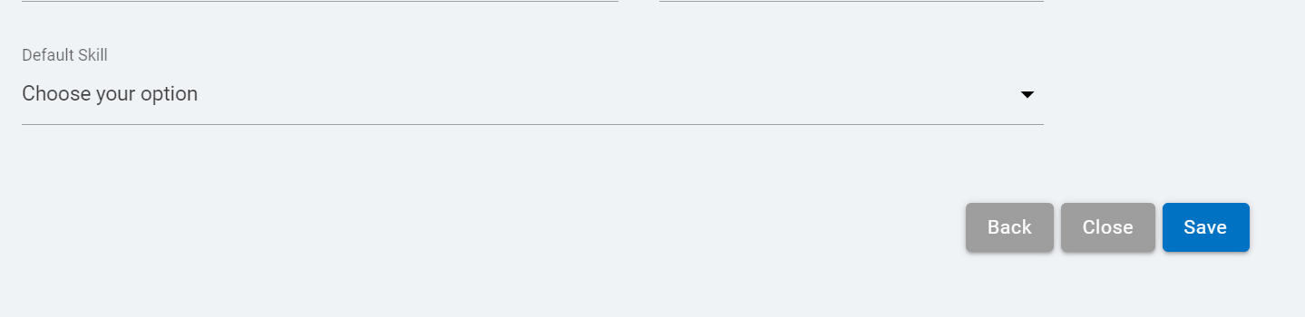
In Default Model, populate the Skills field by
using the Choose A Skill drop-down. Multiple
skills can be added in the Skills field. Enter the Button
Name for the skill. Select the Default
Skill by clicking Choose Your Option
drop-down.
Figure 12. Figure 12 – MULTISKILL
Configuration - Default Model
The Button Name must be unique in the default model.
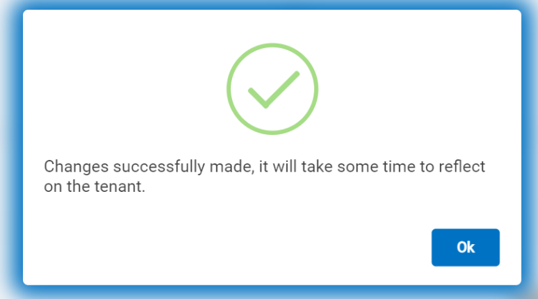
Click Ok to save the configuration. The
following success message appears:
Figure 15. Figure 15 – Success
Message
To delete a skill in the default model, click on the delete
icon corresponding to the skill to
be deleted.
Figure 16. Figure 16 – Delete a
skill in Default Model
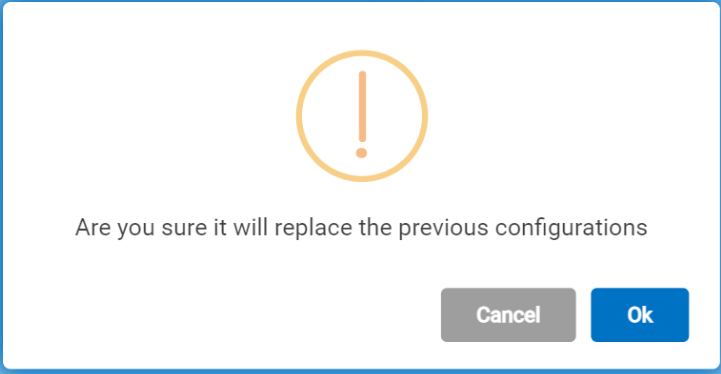
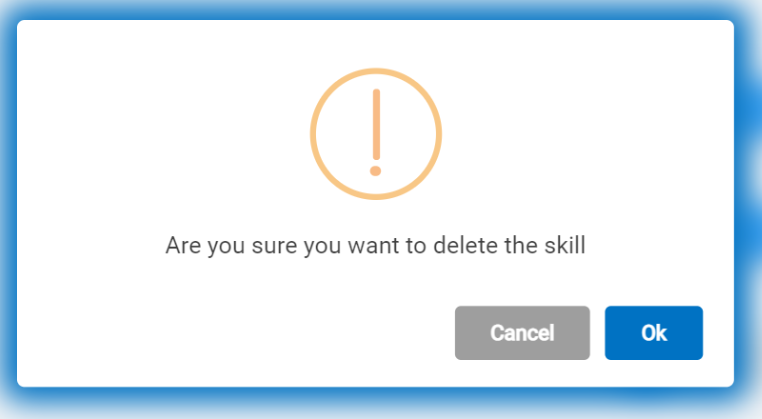
The following confirmation message appears. Click
Ok to confirm the action.
Figure 17. Figure 17 –
Confirmation Message
Multiskill Configuration – Waterfall Model
Perform the following steps for MULTISKILL configuration using
the Waterfall Model:
In the Multi Skill Configuration page, select
Waterfall Model and click
Continue.
Figure 18. Figure 18 – MULTISKILL
Configuration – Waterfall Model
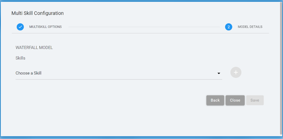
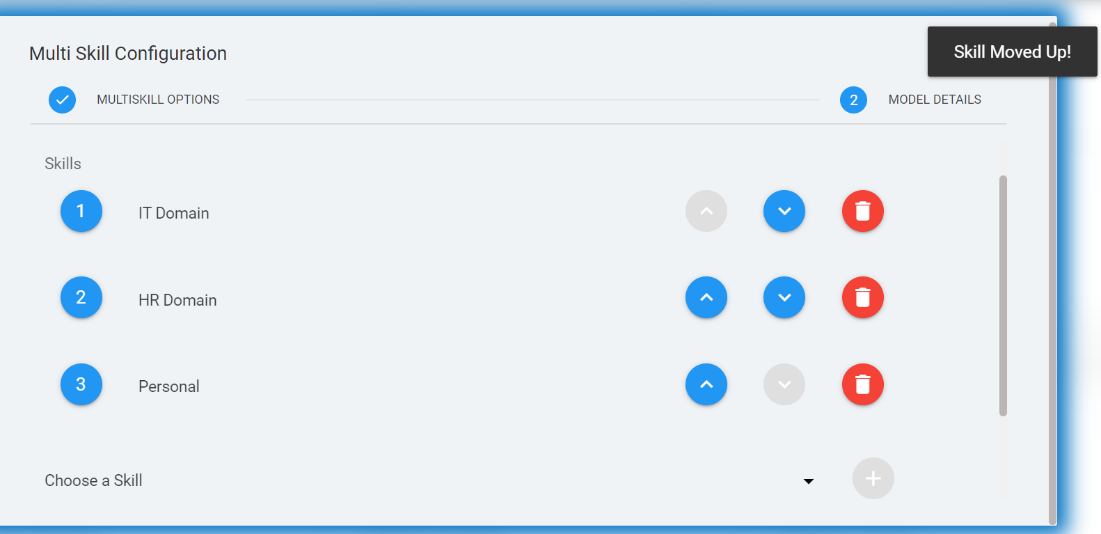
In the Waterfall Multi Skill Configuration, Select
Skills by using the Choose a
Skill drop-down.
Figure 19. Figure 19 – MULTISKILL
Configuration – Waterfall Model
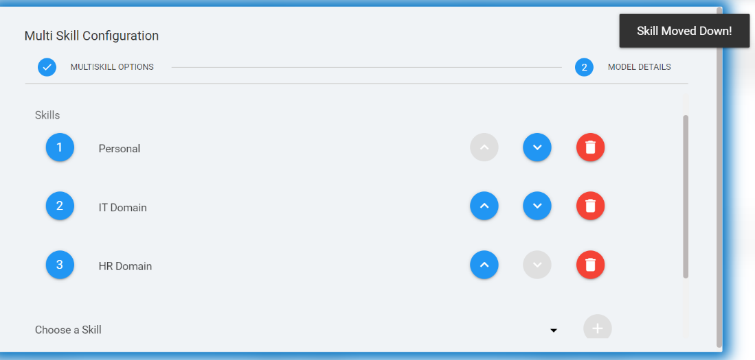
In the waterfall model, user has the options to move the skill
up and down. To move a skill up, click the Move up arrow and to move a skill down, click the Move
down arrow .
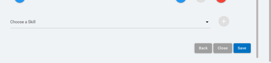
Click Ok to save the configuration. The
following success message appears:
Figure 24. Figure 24 – Success
Message
To delete a skill in the waterfall model, click on the delete
icon corresponding to the skill
to be deleted.
Figure 25. Figure 25 – Delete a
Skill in Waterfall Model
The following confirmation message appears. Click
Ok to confirm the action.
Figure 26. Figure 26 –
Confirmation Message
Multiskill Configuration – Broadcast Model
Perform the following steps for MULTISKILL configuration using
the Broadcast Model:
In the Multi Skill Configuration page, select
Broadcast Model and click
Continue.
Figure 27. Figure 27 – Multi Skill
Configuration Page
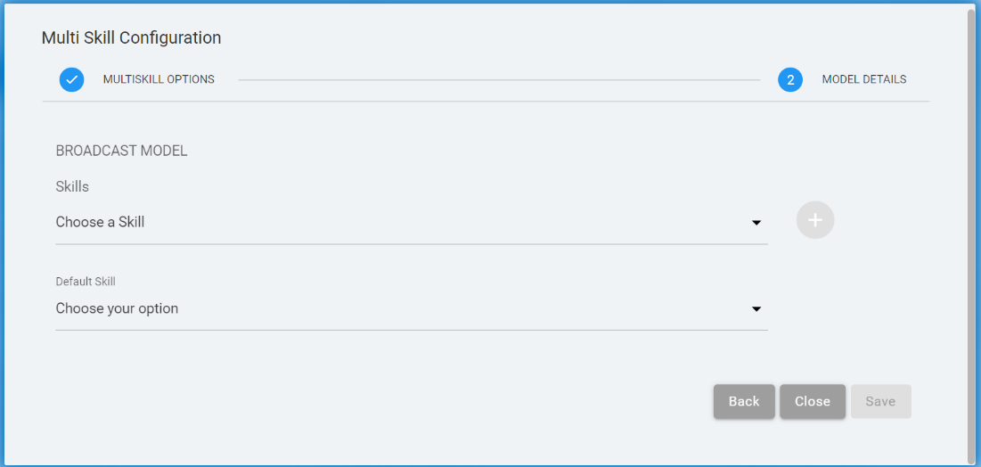
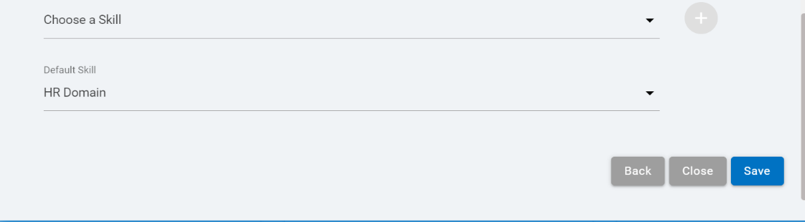
In Broadcast Multi Skill Configuration, select
Skills using the Choose a Skill
drop-down. Select the Default Skill by clicking
Choose your option drop-down.
Figure 28. Figure 28 – Multiskill
Configuration – Broadcast Model
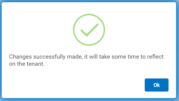
Click Ok to save the configuration. The
following success message appears:
Figure 31. Figure 31 – Success
Message
To delete a skill in the broadcast model, click on the delete
icon corresponding to the skill
to be deleted.
Figure 32. Figure 32 – Delete a
Skill in Broadcast Model
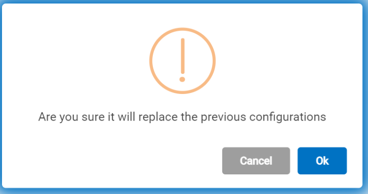
The following confirmation message appears. Click
Ok to confirm the action.
Figure 33. Figure 33 –
Confirmation Message
Multiskill Configuration – Conductor-Follower Model
Perform the following steps for MULTISKILL configuration using
the Conductor-Follower Model:
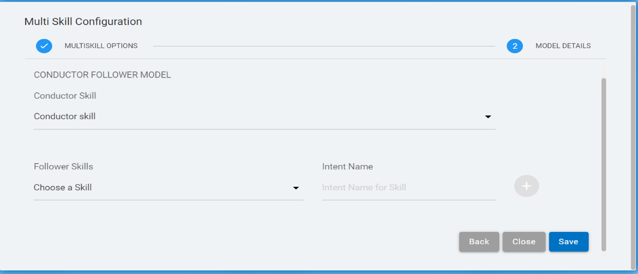
In the Multi Skill Configuration page, select
Conductor-Follower Model and click
Continue.
Figure 34. Figure 34 – Multi Skill
Configuration Page
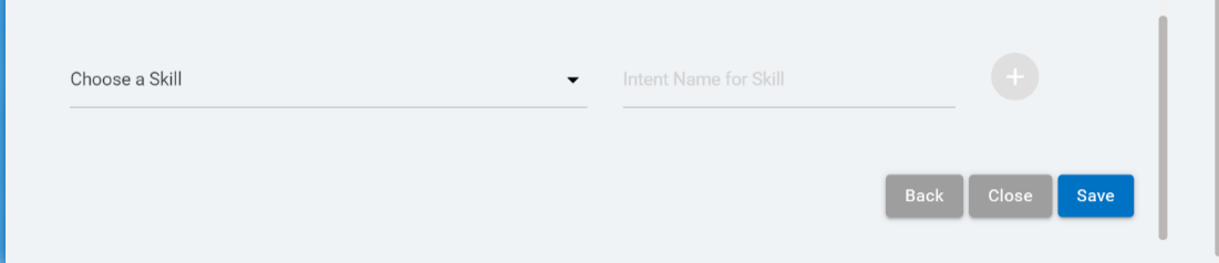
In Conductor-Follower Multi Skill
Configuration, select one Conductor Skill by using
the Conductor Skill drop-down. Then add one or
multiple Follower Skills by using Choose a
Skill drop-down. Enter an Intent Name for
the skill.
To delete a skill in the Conductor Follower
model, click on the delete icon corresponding to the skill to be
deleted.
Figure 39. Figure 39 – Delete a
Skill in Conductor Follower Model
In Conductor Follower model, we must add the Intent value while
adding the Context Variable.
The Skill Intent Name must be unique in the
Conductor Follower Model.
A skill that is configured in Multiskill, cannot be deleted
from the tenant workspace. The user must delete the skill from
Multiskill configuration to delete it from the tenant
workspace.
There must be at least one skill in the Multiskill
configuration.
The skill name must be unique in all the models.
There must be Intent Value added while adding
the Context variable in all the Multiskill models.
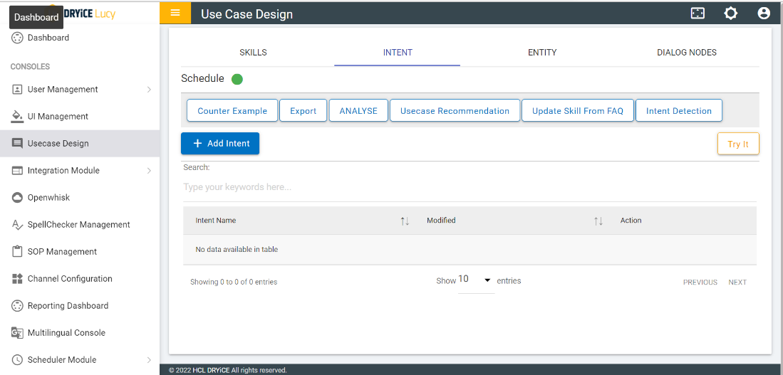
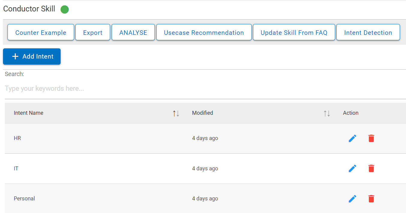
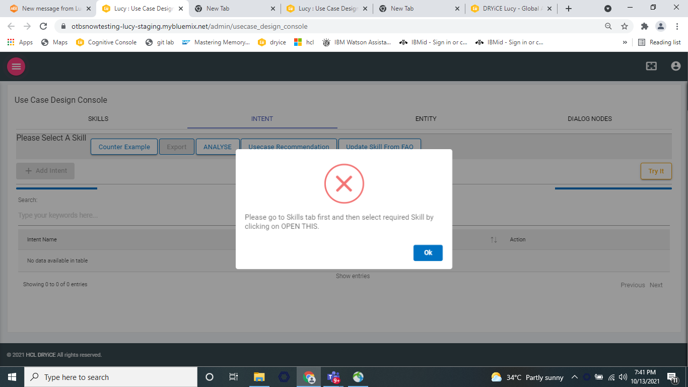
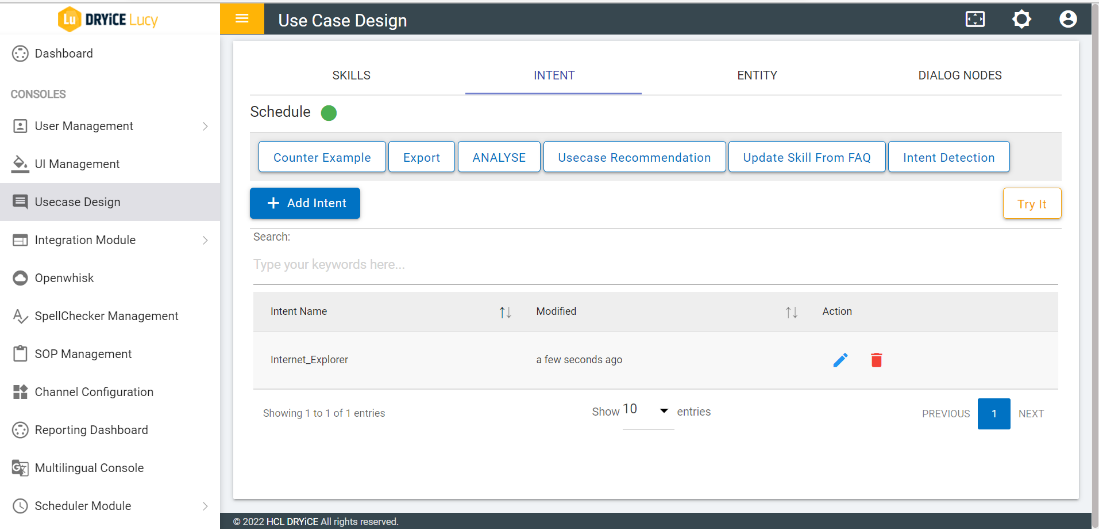
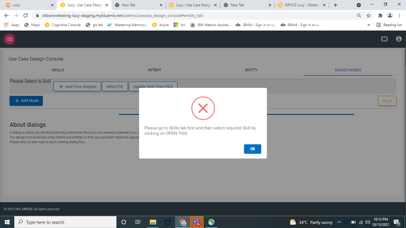
Once the Multiskill configuration is done, select
INTENT tab. If none of the skills is selected,
then a pop up will be displayed saying select a skill.
Progress bar for loading the intents associated with the skill
is visible as shown in the above figure.
If intents are present, the list of intents will be populated
in the intent table. Refer the following figure:
Figure 41. Figure 41 – Intent
Table
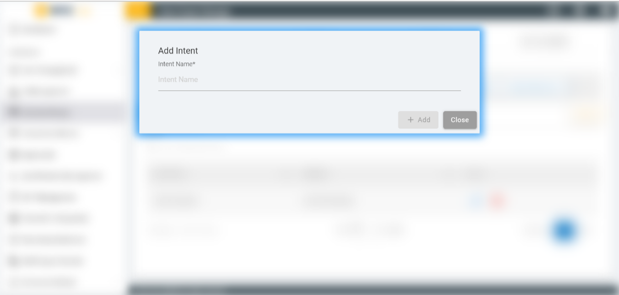
To add new intent, perform the following steps:
Click on ADD Intent button under the
Intent tab. The Add Intent screen appears:
The intent name can contain letters (in Unicode), numbers,
underscores, hyphens, and periods. The name cannot consist of
‘..’ or any other string of only periods. Intent names
cannot contain spaces and must not exceed 128 characters.
Figure 42. Figure 42 – Add
Intent
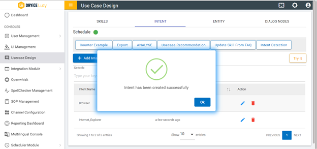
A success message appears and the intent value appears in the
intent table.
Figure 43. Figure 43 – Success
Message
To delete an intent, click on the delete icon corresponding to the intent that you want
to delete.
Figure 44. Figure 44 – Delete
Intent
For handling utterances and intent recognition, variations
provide a robust mechanism to train and recognize user
conversations in natural language. Variations should be added so
the intent recognition system can generalize. New Variations can
also be added to an intent by performing the below steps:
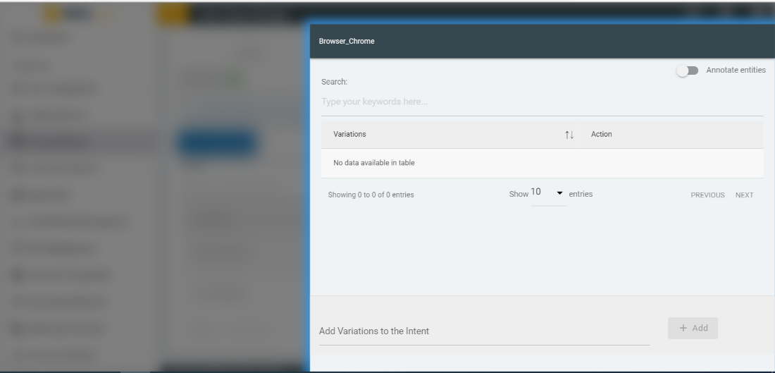
Click on any value of an intent from the intent table under
INTENT tab. A slide navigation slides in
containing the Intent name at the top.
Figure 45. Figure 45 – Add
variation to an intent
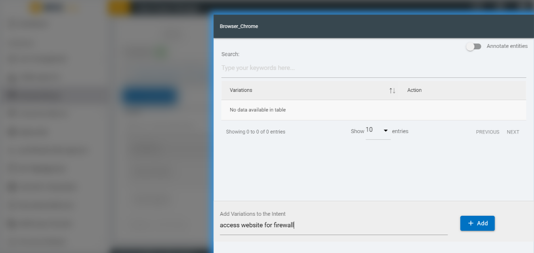
Add a new variation and submit it by clicking on
Add button.
Figure 46. Figure 46 – Add
Variations to the Intent
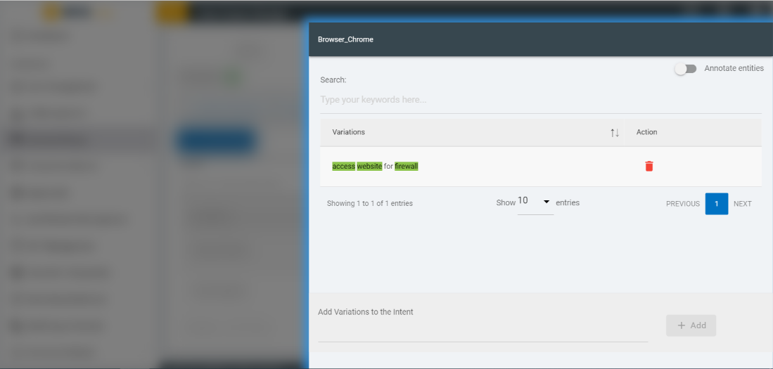
The newly added variation appears in the variation table as
sown below.
Figure 47. Figure 47 – Variation
added to the Intent
You can delete the variation by clicking the delete icon corresponding to the variation.
Intents can also be edited from the main intent page, click on
edit icon for which the entity name user wants to edit it.
Figure 48. Figure 48 - Edit
Intents
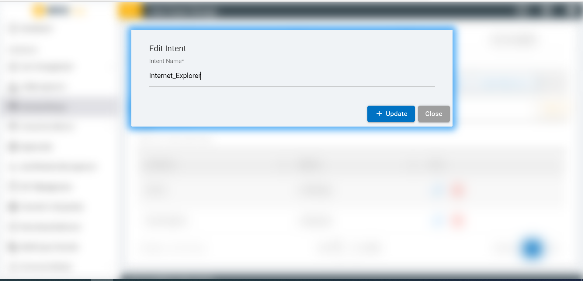
A modal will open to edit the intent name, where you can make
changes as needed.
Figure 49. Figure 49 - Edit Intent
Name
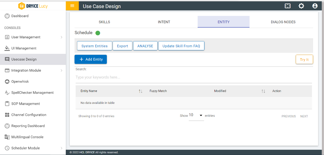
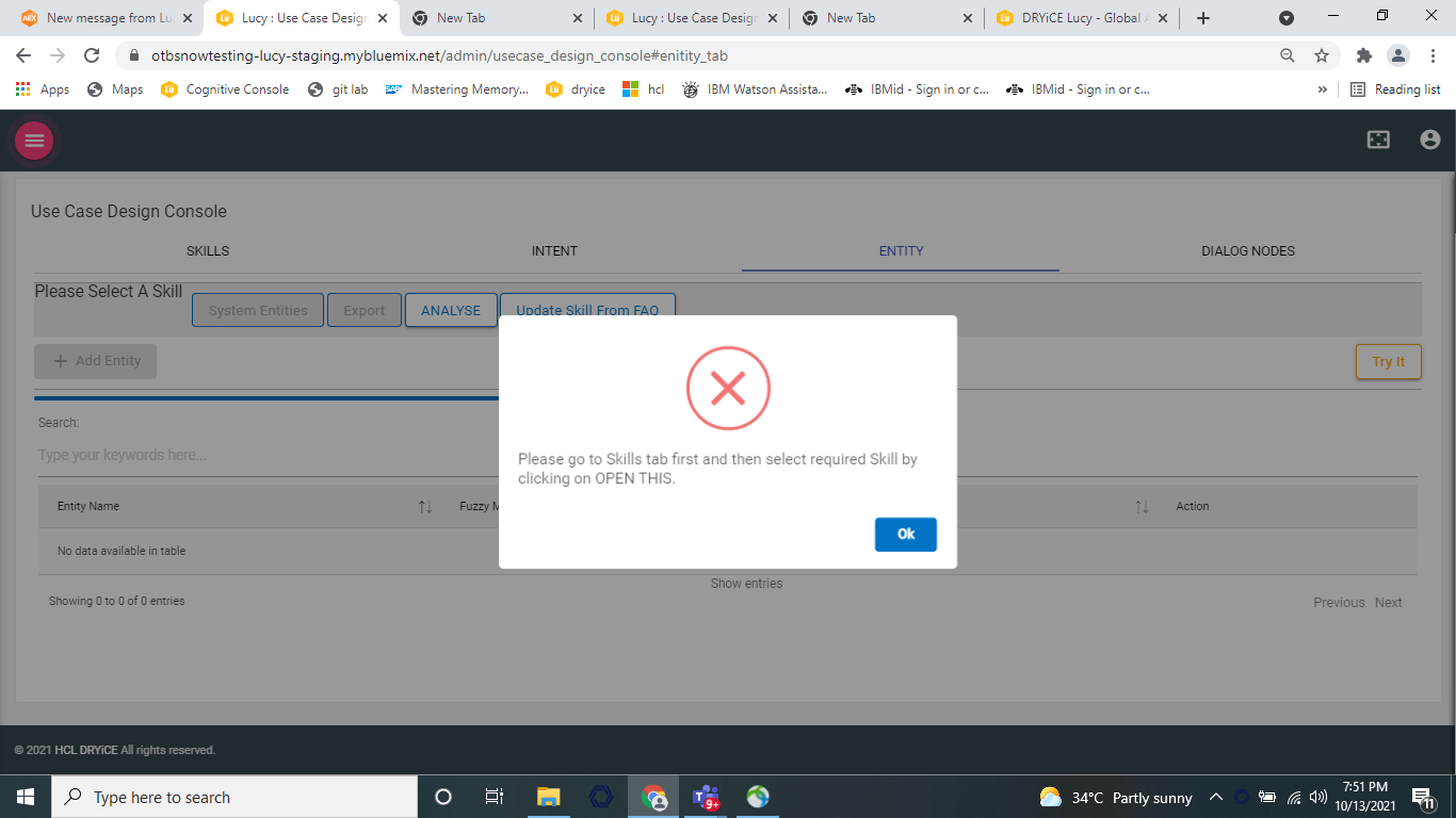
Now, select the ENTITY tab. If none of the
skill is selected, then a pop up will be displayed saying select a
skill.
Figure 50. Figure 50 – Entity
Tab
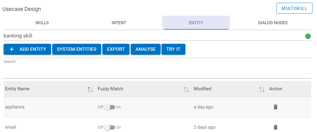
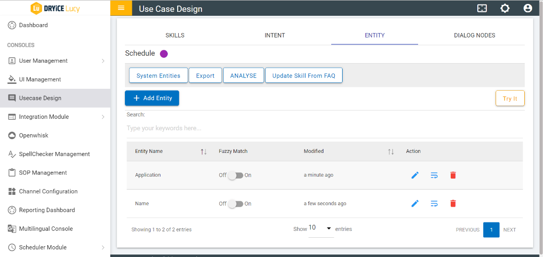
If the entities are present, the list of entities will be
populated in the entity table.
Figure 51. Figure 51 – List of
Entity
The following columns are available:
Entity Name: Displays the list of Entities.
Fuzzy Match: Contains the toggle buttons that display the
status of fuzzy logic of the entity.
Modified: displays the time when the property of the entity was
last changed.
Action: contains the delete icon to delete the corresponding
entity.
Perform the following steps to add Entity.
Click on ADD Entity button present under
ENTITY tab. The Add Entity screen appears:
Figure 52. Figure 52 – Add
Entity
The entity name can contain letters (in Unicode), numbers,
underscores, and hyphens. Do not include spaces in the name. The
name cannot be longer than 64 characters. The name cannot be
prefixed with ‘sys-’ as it is reserved for system
entities.
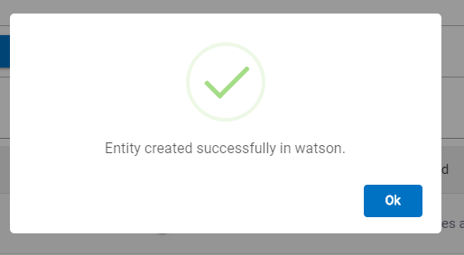
Add the Entity by clicking on ADD button. A
success message appears:
Figure 53. Figure 53 – Success
Message
The newly added Entity appears in the Entity table.
Figure 54. Figure 54 – Entity
Table
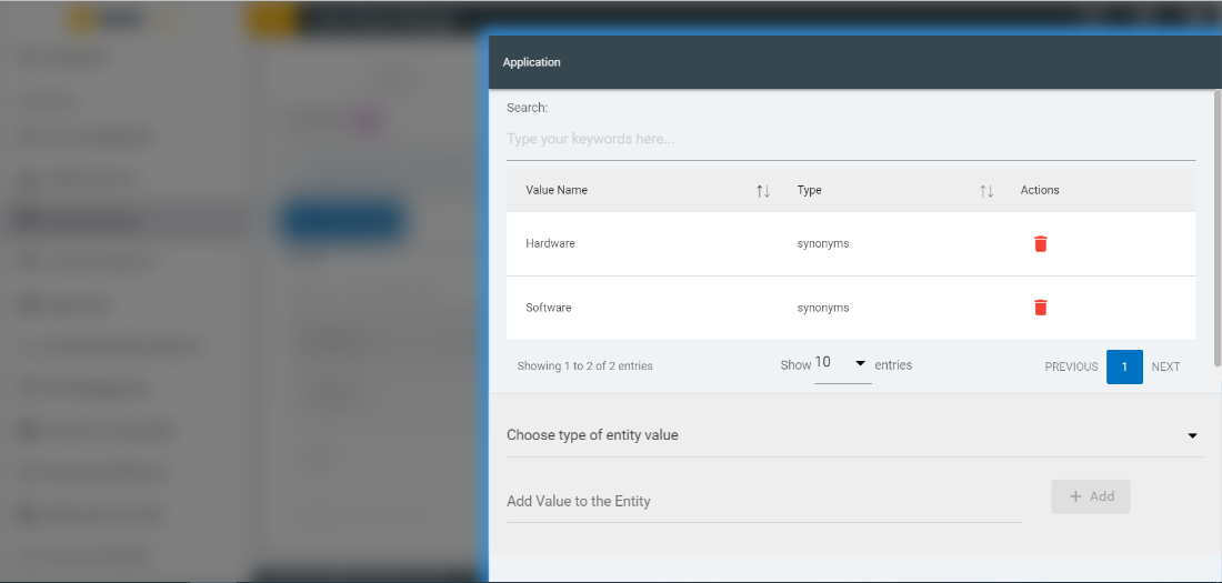
Values can be added to an Entity by performing the following
steps:
Click on a value of an entity in entity table under the
ENTITY tab. A side navigation slides in containing
the entity name at the top.
Figure 55. Figure 55 – Add value
to the Entity
Add a new entity value and submit it by clicking on
Add button present there.
Select the type from the dropdown. Two types are
available:
Pattern option allows to put regular
expressions for values.
Synonym option allows to match the text
itself.
Figure 56. Figure 56 – Add value
to the Entity
The newly added entity value appears in the entity value
table.
To delete an entity value, click on delete icon corresponding to the entity value
that you want to delete.
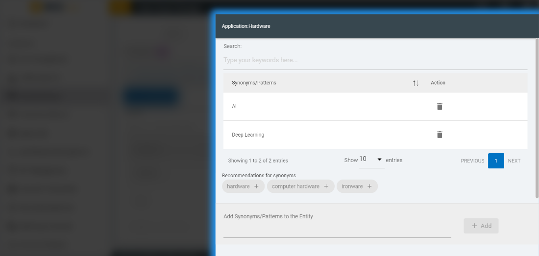
Take the following steps to add synonyms to the Entity:
Click on any value of an entity in entity value table to add
synonyms to it. A side navigation slides in containing the entity
name at the top.
Figure 57. Figure 57 – Add
Synonyms to the Entity
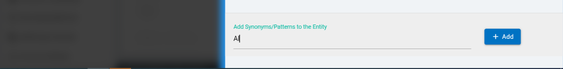
Add a new synonym and submit it by clicking on
Add button.
Figure 58. Figure 58 – Add
Synonyms to the Entity
The newly added synonym value appears in the entity value
table.
Figure 59. Figure 59 – Add
Synonyms to the Entity
To delete a synonym, click on delete icon corresponding the synonym that you
want to delete.
Entity names can be edited by clicking on edit icon for which
the entity name user wants to edit.
Figure 60. Figure 60 - Edit
Entity
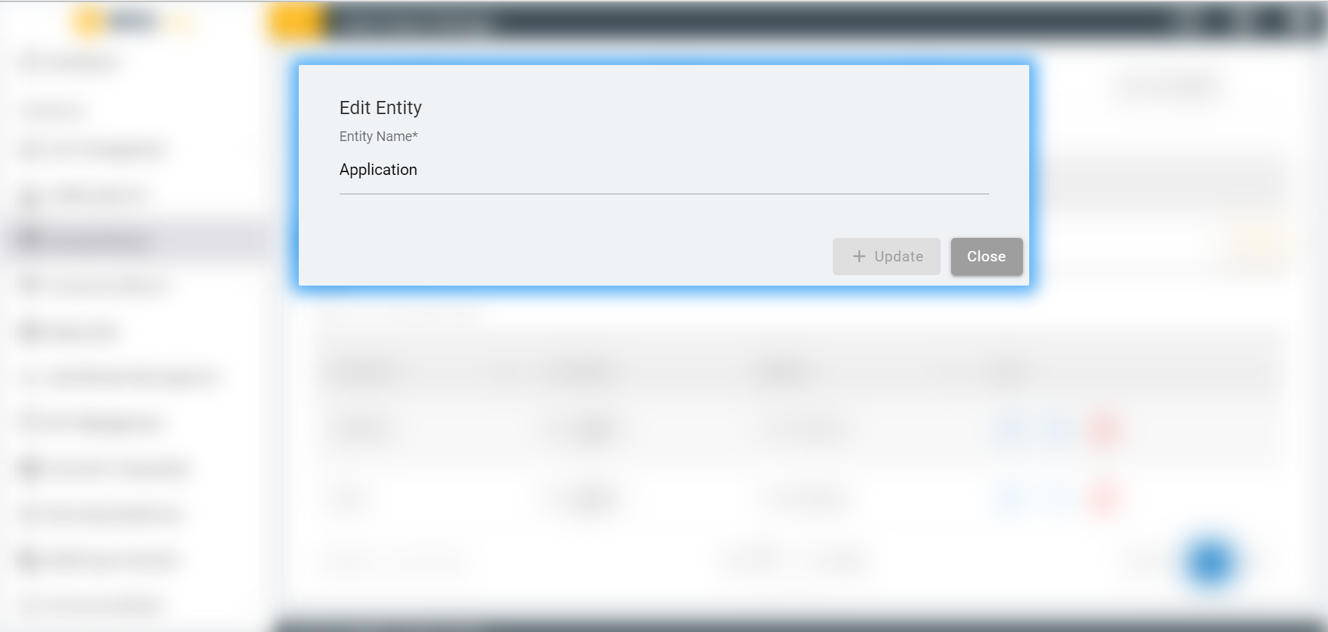
A dialog box will open to edit the entity name:
Figure 61. Figure 61 - Edit Entity
Name
Perform the following steps to enable system entities:
Pre-built entities allow users to extract and work on commonly
used language references, such as dates, numbers, etc.
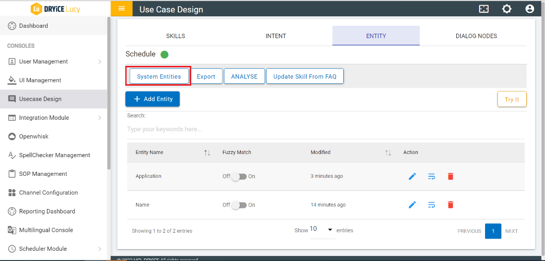
Click on the System Entities button under the
ENTITY tab.
Figure 62. Figure 62 – System
Entities
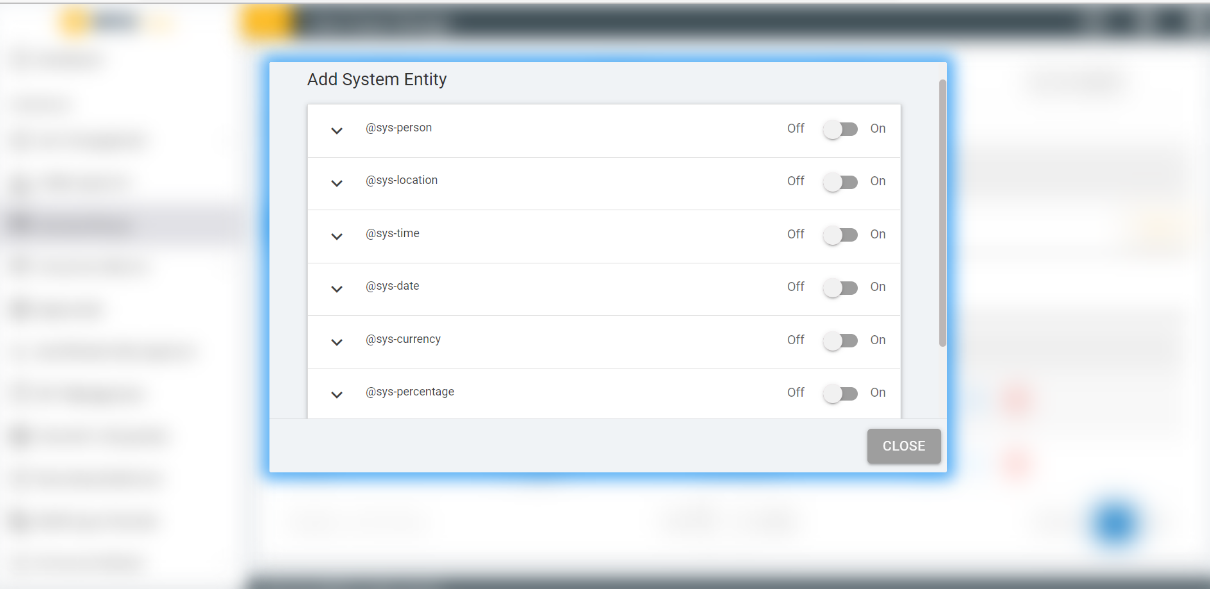
A window appears showing the available system entities. The
console provides several system entities, which are common
entities that you can use for any application. Enabling a system
entity makes it possible to quickly populate your skill with
training data that is common to many use cases.
Figure 63. Figure 63 – Add System
Entity
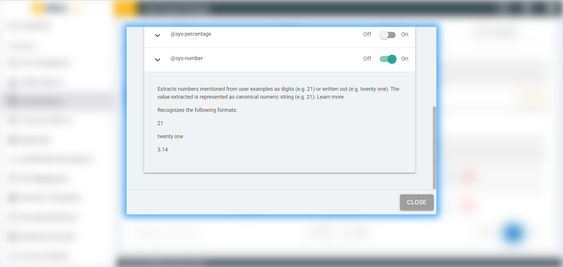
Click on the toggle of any system entity to enable it. For
example, the @sys-number system entity matches any numerical value,
including whole numbers, decimal fractions, or even numbers written
out as words.
Figure 64. Figure 64 – Enable
System Entity
You can now use the enabled entities in you dialog nodes
directly.
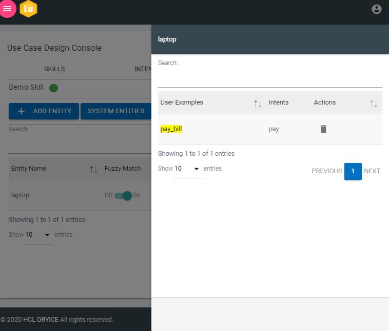
Contextual Entities can also be used with UCD console; these
entities allow BigFix AEX to detect user context from the
utterance. Contextual entities provide a faster way of recognizing
newer entities without explicitly creating them every time.
The value which is annotated in a variation of the intent will
reflect in an entity by yellow color.
Figure 65. Figure 65 - Contextual
Entities
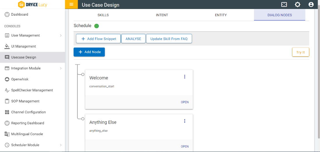
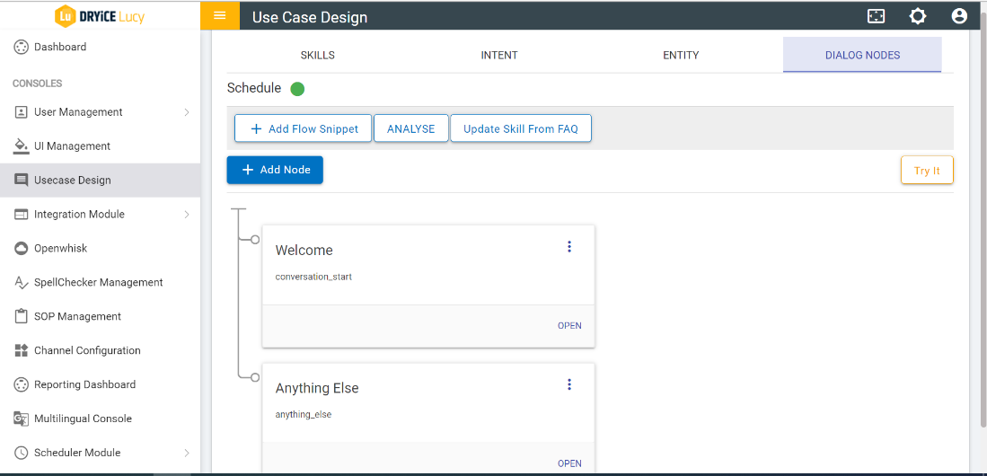
Select DIALOG NODE tab. If none of the skill
is selected, then a pop up will be displayed saying select a
skill.
Figure 66. Figure 66 – Dialog
Nodes
The dialog node’s id and description (optional) appear on
the card.
Figure 67. Figure 67 – Dialog
Nodes Cards
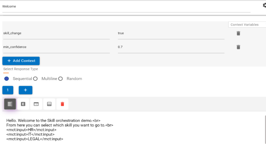
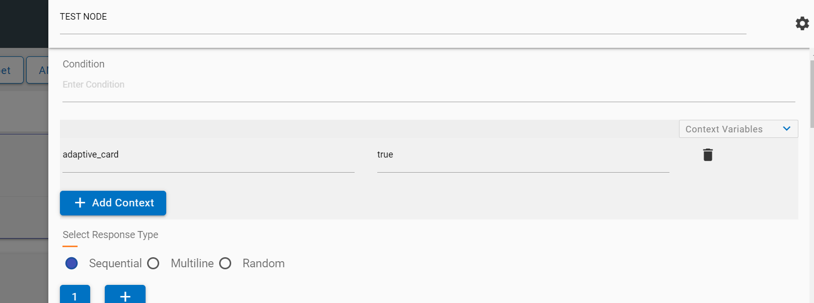
While adding the Context variable,
skill_change should be in true condition.
While configuring the Anything else node, the
anything_else condition must be
‘True’.
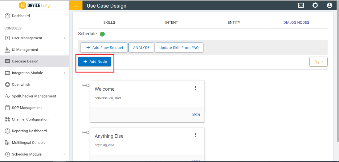
To add new nodes, click on ADD NODE button
under the DIALOG NODES tab.
Figure 68. Figure 68 – Add New
Node
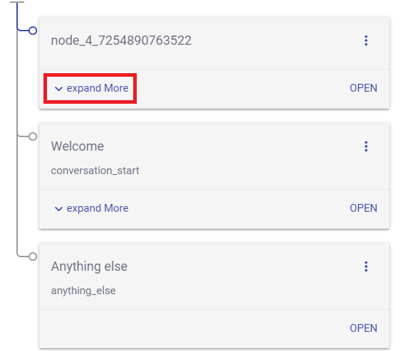
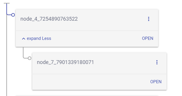
To see the child nodes associated with the Node, click on
Expand More.
On clicking of Expand Less, the child nodes
collapse.
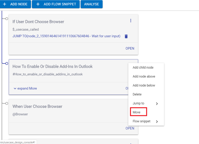
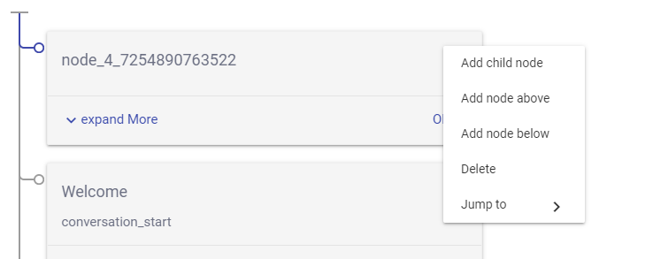
The following actions can be performed on each available node
by clicking on the kebab menu (three dots menu) placed on each
node:
Add Child Node: A new node will be added as child
Add Node Above: A new node will be added above the node.
Add Node Below: A new node will be added below the node
Delete: Deletes the Node
Move: Move within Nodes
Moving a dialog node that you have created can be moved
anywhere in the dialog tree. You might want to move a previously
created node to another area of the flow to change the
conversation. You can move nodes to become siblings or peers in
another branch.
On the node if you want to move, click 3 dots icon, and then
select Move.
Figure 71. Figure 71 - Move Nodes
Option
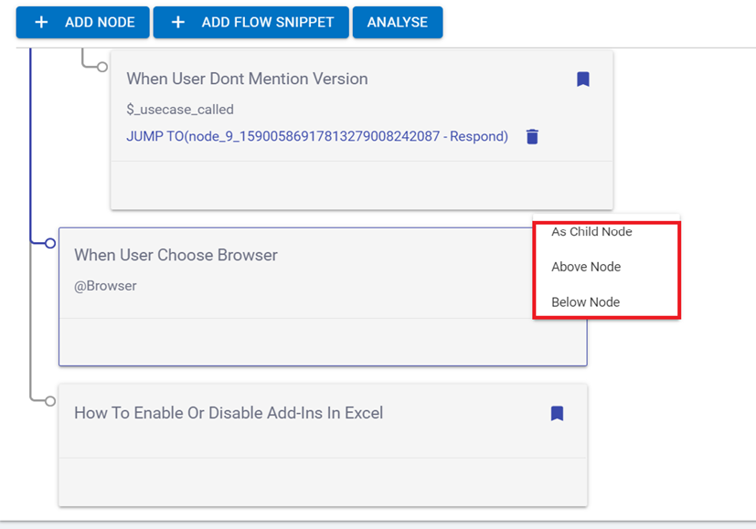
Select a target node that is in the tree near where you want to
move this node. where user will find three options i.e., As child
node, below node and above node as shown in fig.
Figure 72. Figure 72 - Move Relative to
Target Node
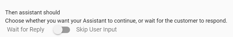
Jump to: Jumps to the following options as defined:
Response
Assistant Recognize
Wait for User Input
Figure 73. Figure 73 – Addition
Node Menu
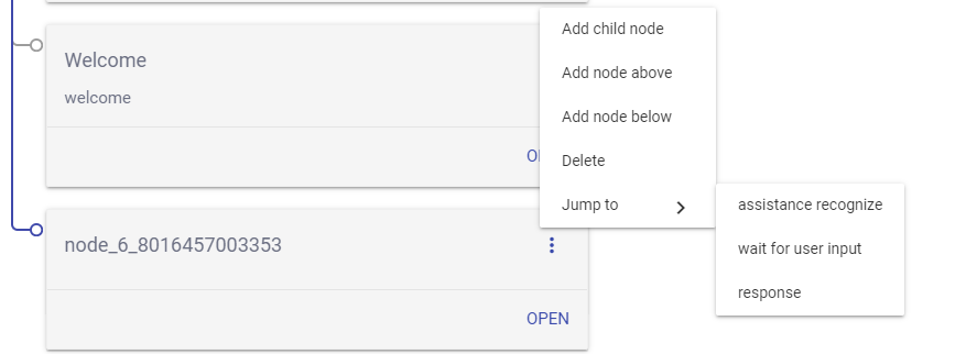
Jump to: In order to perform “Jump
to” on a node, click on type of Jump to selector i.e.
Wait for User Input, Assistance
Recognize, or Response. Select
destination node by clicking on moving point (MP icon )
Figure 74. Figure 74 – Jump
toFigure 75. Figure 75 – MP
Icon
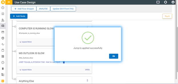
The source node of Jump to option will be labeled with Jump to
(destination node id) after a pop-up message stating that Jump to
has been applied successfully on Watson.
Figure 76. Figure 76 – Success
Message
To delete the ‘Jump to’, click on delete icon
present next to Jump to (destination node id) label.
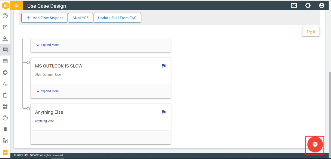
Once Jump to has been initiated but needed to be cancelled
before selecting a destination node; in that case click on cross
icon present on the right bottom of the console.
Figure 77. Figure 77 – Jump
to
By clicking on Open placed on each node, you
can view the form where you can perform multiple actions like view
or modify the settings of the node, add context, and add Response
etc.
Figure 78. Figure 78 – Side
Navigation form for Node
Click on the setting icon to
check the settings of form. The following screen appears:
Figure 79. Figure 79 – Node
Settings
To set digressions, click on that toggle button of digression
and to set multi condition response, click on toggle button of
MCR.
If MCR is enabled, the form shows the fields specific to MCR
form.
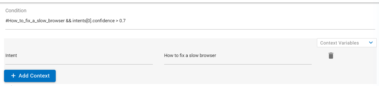
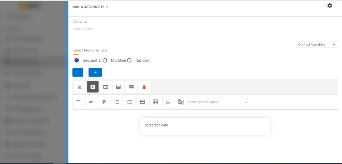
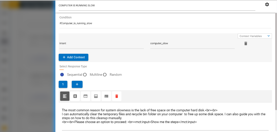
When dialog node form is opened for first time, it shows
standard form with fields and buttons i.e., node name, condition,
add context and response type.
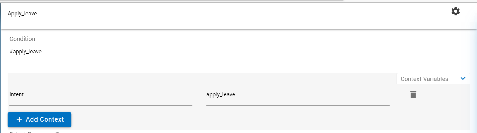
Enter Node Name and Condition.
Click on ADD CONTEXT and ADD
RESPONSE to add new context and response respectively.
Refer the image below to understand how to add conditions, context
variables and Responses.
Figure 80. Figure 80 – Node
Settings (Cont.)
The Intent name must be prefixed with # and the Entity name
must be prefixed with @ to match the condition. You can also use
logical operators such as &&, || and! in conditions. To
save any entity/intent matched as a context variable use the format
given in the picture above.
The name of context variable can contain any upper and
lowercase alphabetic characters, numeric characters (0-9), and
underscores. You can include other characters, such as periods and
hyphens, in the name. However, if you do so, then you must specify
the shorthand syntax $(variable-name) every time you subsequently
reference the variable.
The value of context variable can be any text that you want,
but if you want to capture an intent/entity from user input, use
the following expression syntax to capture it:
<?@entity_name?>.
Clicking anywhere in the form submits the fields.
Addition or deletion will be enabled once the fields are
submitted successfully. You can add more responses by clicking on
the ADD RESPONSE button:
Figure 81. Figure 81 – Node
Settings (Cont.)
If there is more than one response in a dialog you can choose
one of the three settings that the console provides.
Sequential: The system returns the first response variation the
first time the dialog node is triggered, the second response
variation the second time the node is triggered, and so on, in the
same order as you define the variations in the node.
Random: The system randomly selects a text string from the
variations list the first time the dialog node is triggered, and
randomly selects another variation the next time, but without
repeating the same text string consecutively.
Multiline: When the response is shown to the user, both
response variations are displayed, one on each line. For example,
if you have 3 response variations: Hi, Hi there, and Hi there
friend. The multiline response would be as follows:
Hi
Hi there
Hi there friend.
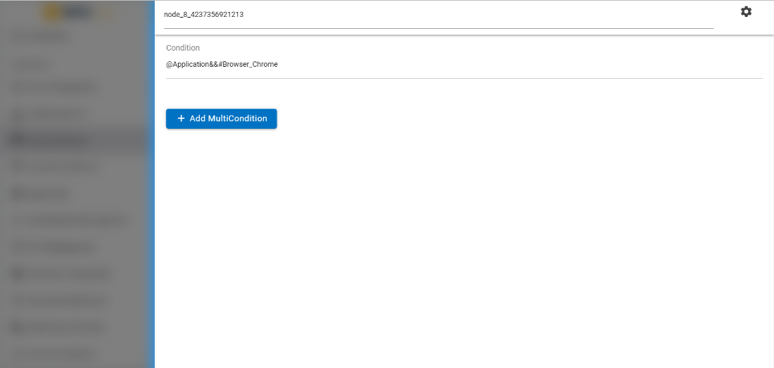
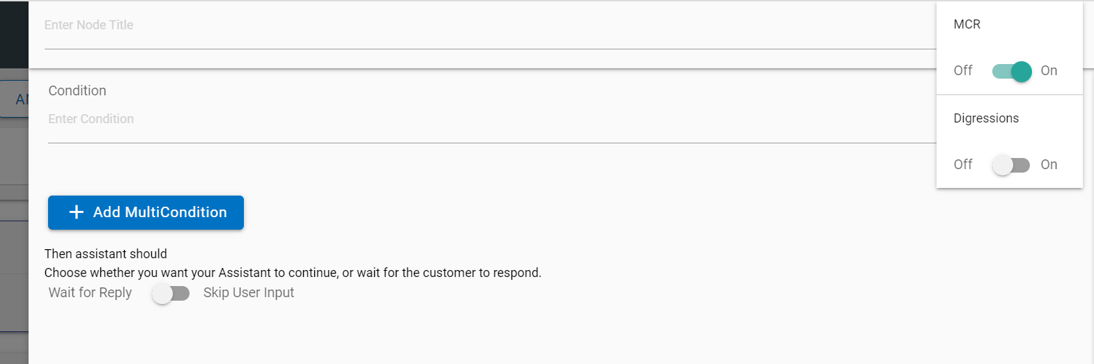
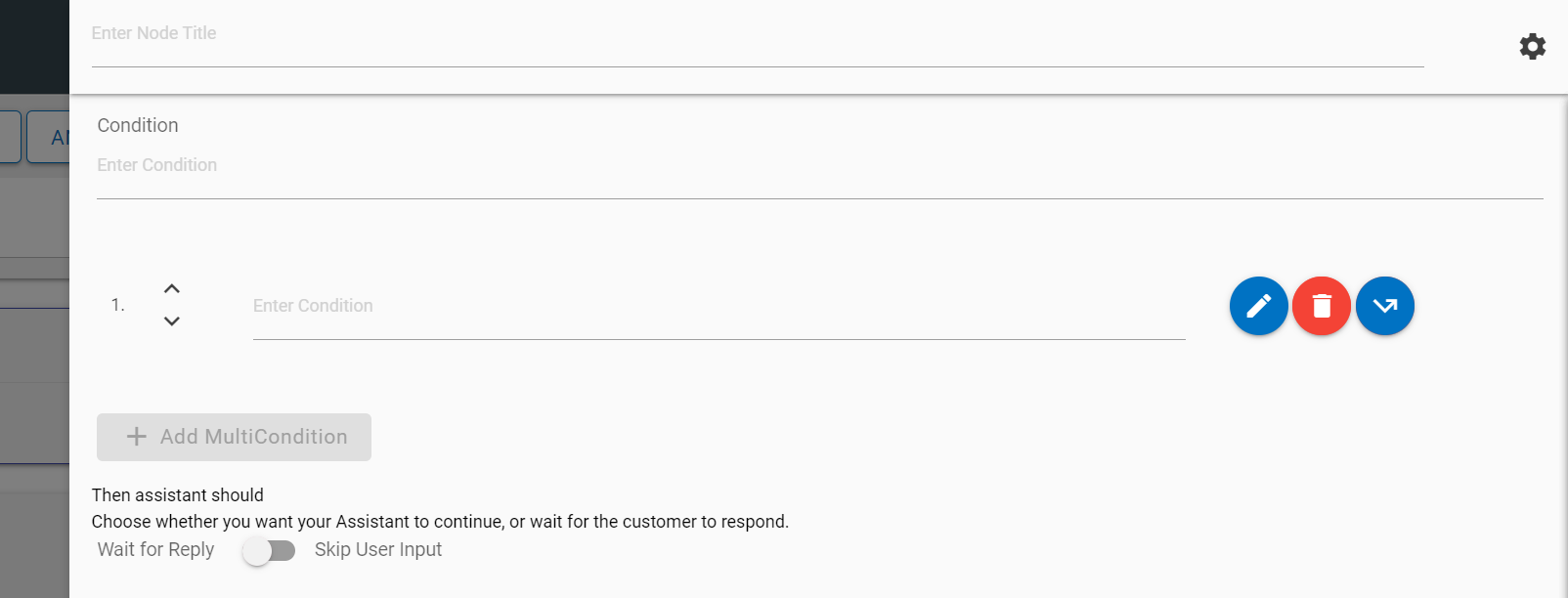
When MCR is enabled, the MCR form is displayed with fields and
button i.e., node Title,
Condition and an “ADD MULTICONDITION”
button. The pop-up message will be displayed stating that MCR is
enabled. By default, the ADD MULTICONDITION button is disabled.
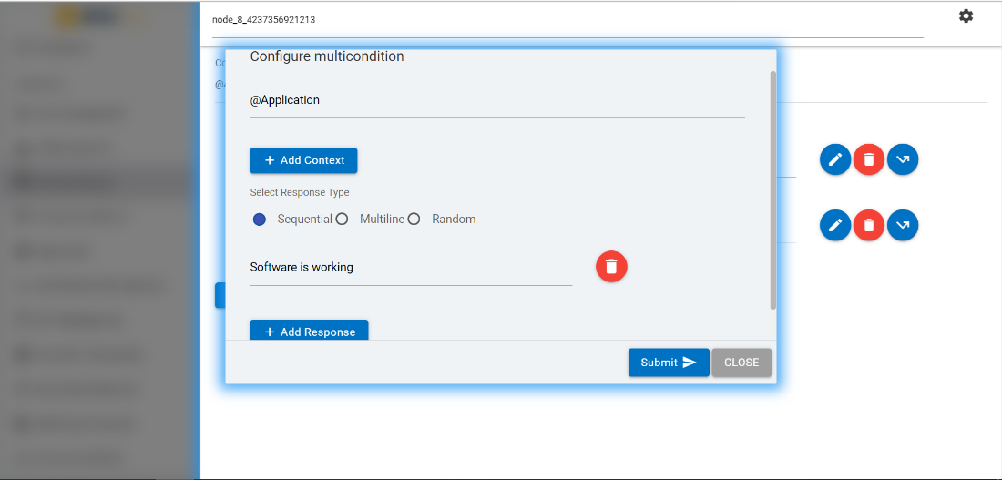
Perform the following steps to configure multicondition:
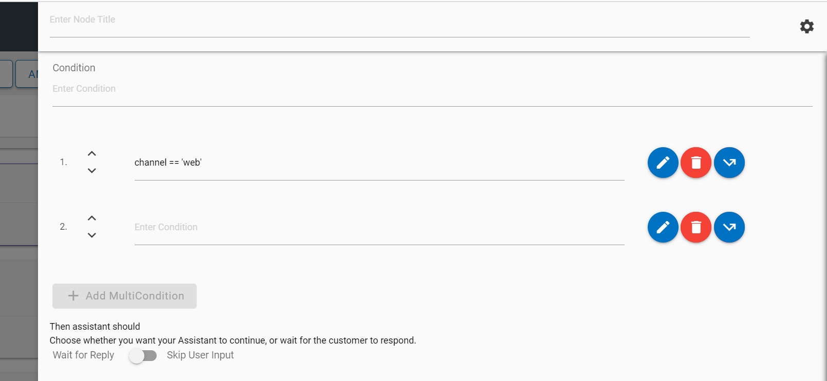
All these fields on MCR form get submitted on focus out.
Addition or deletion options are enabled once the fields are
submitted successfully.
Click on edit icon associated with each multicondition to add
other values to that multicondition. A screen appears with fields
i.e., Condition, Add Context,
Response Type with a Submit button.
The condition field inside the edit screen will have same value
as the multicondition which can be edited.
Click on ADD CONTEXT and ADD
RESPONSE to add new context and response of the
multicondition respectively.
All these fields on MCR modal form will get submitted by
clicking on the Submit button below.
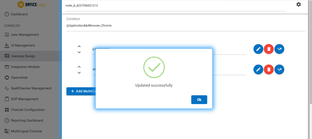
A success message appears once the form is submitted
successfully. Addition, Deletion
or Edit of new multicondition will be enabled once
the edited details are submitted successfully.
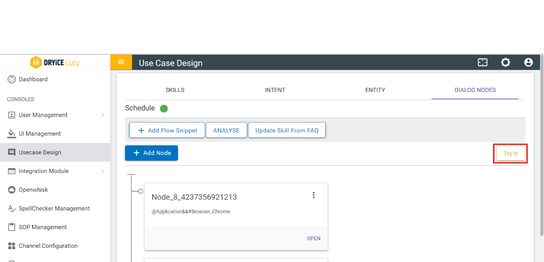
You can chat and test the use cases configured if they are
responding as per the requirement or not. Perform the following
steps to do so:
Click on TRY IT on the UCD Console under
Dialog Nodes tab. A chat console appears.
Figure 87. Figure 87 – Usecase
Design Console
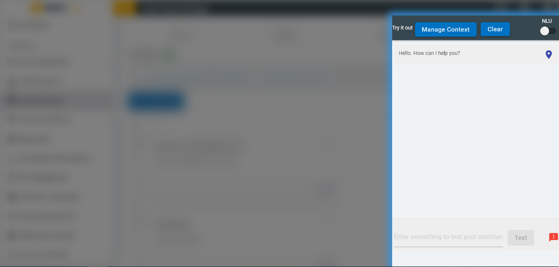
The Try it out panel slides in as shown in the
following image. Use the text area at the bottom to enter your
query and click on TEST to send it.
Figure 88. Figure 88 – Try it out
Panel
The response looks like follows: Figure 89. Figure 89 – Test Response
Here you can see the console detected the entity @sys-person:Lisa. Click on the
blue location pin to open the dialog node that was
triggered by your input.
Figure 90. Figure 90 – Test Response (cont.)
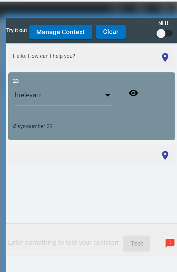
Click on the CLEAR button on the top to remove any previous chat from the
Try it out panel.
Click on the MANAGE CONTEXT button to create or make changes to context
variables.
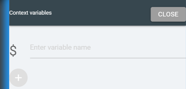
Figure 91. Figure 91- Context Variables
Enter the variable name for context and then click on the plus (+) icon to add value
as desired.
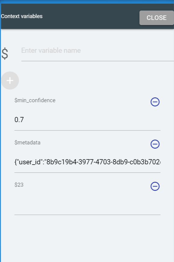
Figure 92. Figure 92 – Context Variables
If any intents are matched, it will show up as follows. Here the intent #turn_off is
detected:
Figure 93. Figure 93 – Context Variable
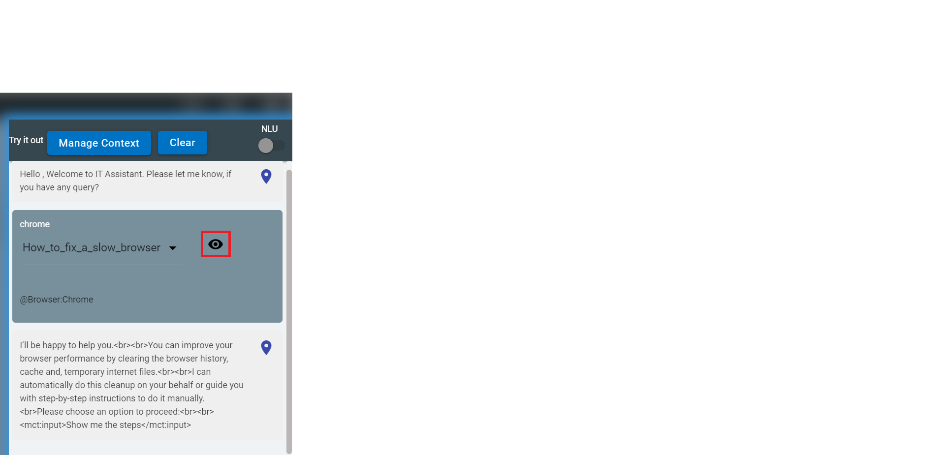
Clicking on the eye icon opens the list where it
shows all the intents and the confidence score of the intent for the input query.
Figure 94. Figure 94 – Context Variable
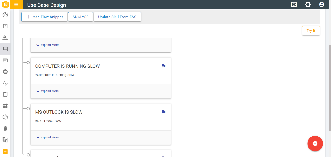
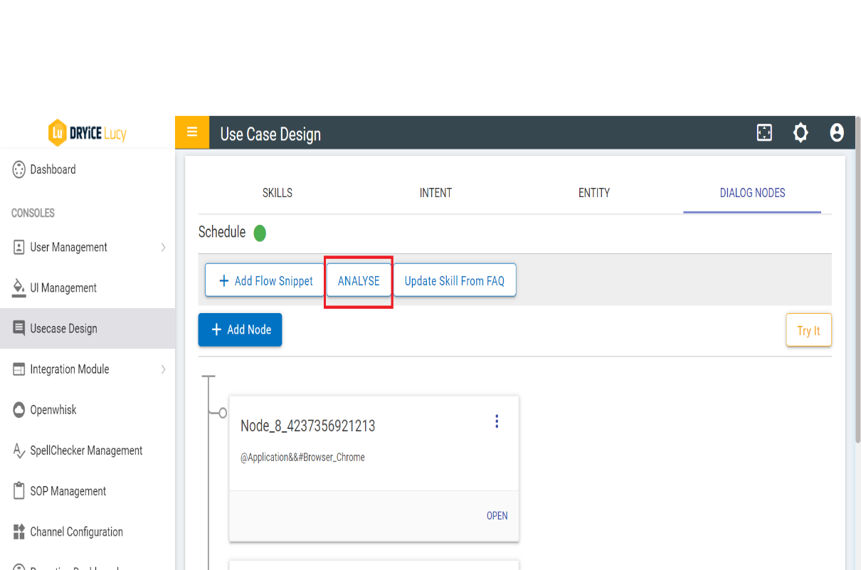
The Analyse feature lets the user upload the usecases and its variations and
verify what is the predicted intent and usecase for them.
The ANALYSE button is present under Intent, Entity and Dialog Nodes tab as shown in
below figure:
Figure 95. Figure 95 – ANALYSE Tab
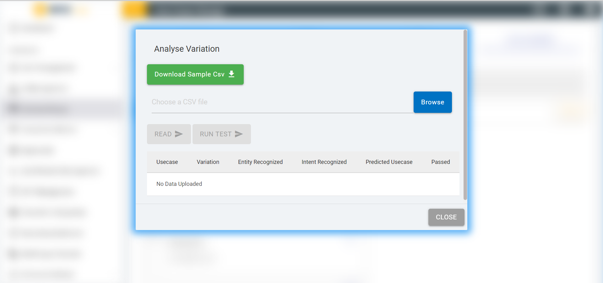
When ANALYSE button is clicked the following screen pops up:
Figure 96. Figure 96 - Analyze Variation Screen
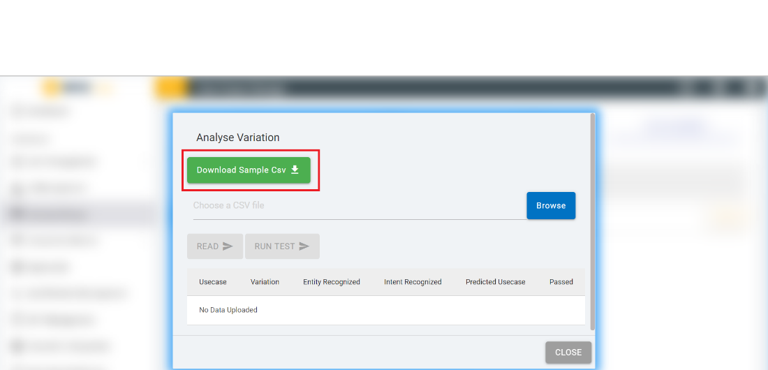
Clicking on DOWNLOAD SAMPLE CSV downloads a csv file which is a reference
template to upload the usecase variations file.
Figure 97. Figure 97 – DOWNLOAD SAMPLE CSV
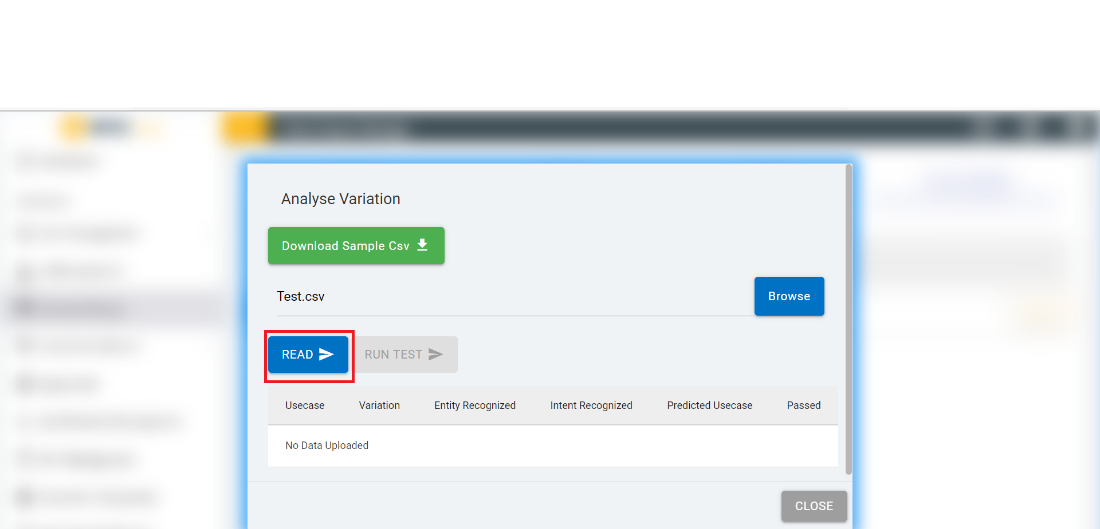
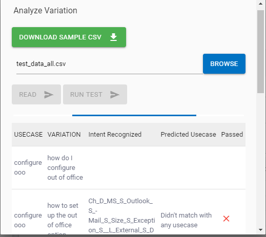
Once the file is uploaded the READ button gets enabled.
Figure 98. Figure 98 – Analyze Variation
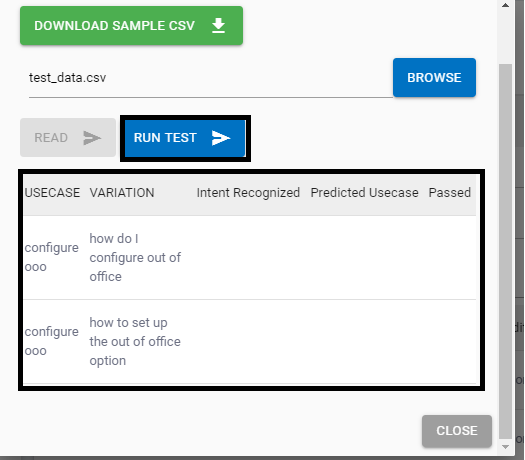
When we click on Read button, the data is uploaded from the csv file to the table on
the screen and the RUN TEST button gets enabled. Refer the below screenshots:
Figure 99. Figure 99 - Upload of Usecase Variations CSV
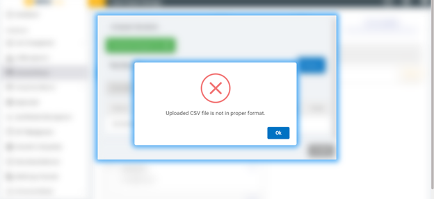
If the CSV is in improper format the following error alert appears as shown in the
figure below:
Figure 100. Figure 100 - Error alert
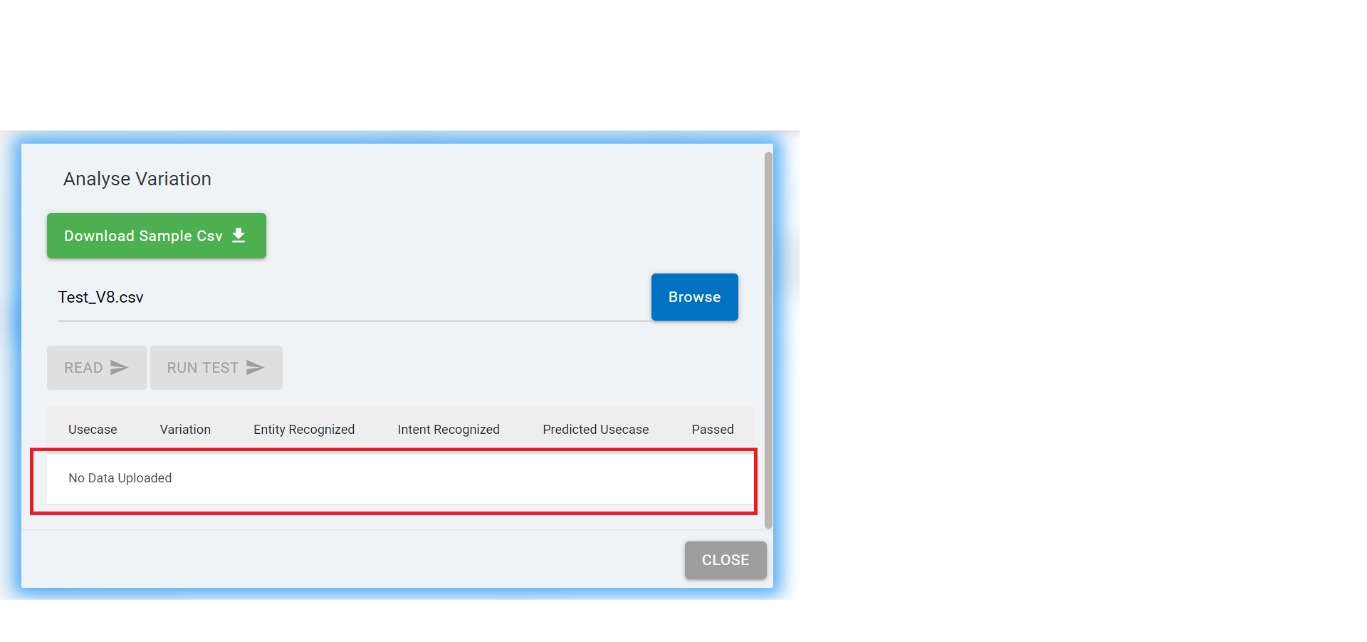
When there is no data in the csv file and it is uploaded, the Read button gets
disabled, and the table shows the text “No data uploaded”.
Figure 101. Figure 101 – ‘No data uploaded’ Message
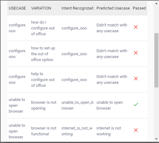
Once the rows from CSV are read and the data on the screen is uploaded and displayed,
the RUN TEST button is enabled. On the click of RUN TEST button, the analysis of
variations for all the data rows starts.
The screen displays the progress of the analysis for all the rows of the table and the
RUN TEST button is disabled. Once it’s completed the progress bar disappears.
On the upload of a different file the READ button gets enabled.
Figure 102. Figure 102 – Run TestFigure 103. Figure 103 – Run Test (Cont.)WYSIWYG Use Case Design Console Enhancements
The WYSIWYG (What You See Is What You Get) editor in the Use Case Design Console provides
a low-code approach to building conversations and dialogues for BigFix AEX. This provides
a simpler point and click editable view to create rich HTML and plain text BigFix AEX
responses, which are the same as what the end user would see when using BigFix AEX.
This reduces the need for cognitive SMEs to write HTML tags explicitly and makes the use
case/response creation easy.
The WYSIWYG editor is the default setting for the Use Case
Design console and does not need any configuration. The following part of this section
highlights the key functionalities of the editor:
The default editor, present in the
earlier versions as shown in the below figure, has been replaced by the new WYSIWYG
editor.
Figure 104. Figure 104 – Editor in BigFix AEX Releases Before 6.0
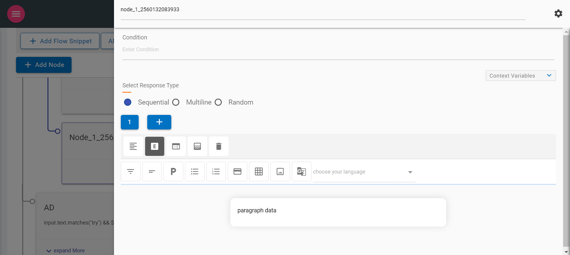
Since 6.0, the default editor for any node in the use case design console looks
like the following figure (opens in the side navigation bar):
Figure 105. Figure 105 – WYSIWYG Editor in all releases after 6.0
The following are the Key items in the new response panel:
Node Title & Settings (Gear icon )
Context Variables
Select Response Type
Node title
Node Title can be edited to provide a meaningful node name
Figure 106. Figure 106 – Node Title
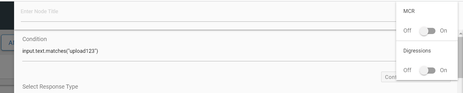
Clicking on the gear icon on the right side of the node title displays the following options:
MCR - On enabling (MCR) Multi Condition Response toggle, the
editor changes to a multi-condition editor.
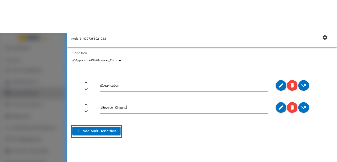
Figure 109. Figure 109 – Multi Condition Response
It allows users to add multiple conditions by clicking on the “Add Multi
Condition” button. Here, the response editor is similar to the early
versions.
Figure 110. Figure 110 – Add Multi Condition ResponseFigure 111. Figure 111 – Edit Multi Condition Response
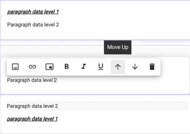
MCR nodes can be moved up and down by clicking on the Up/Down arrow buttons corresponding to the node that you want to move.
Figure 112. Figure 112 - Move Multicondition Node
The following actions can be taken on each condition:
Edit: Each condition can be edited by using the edit icon corresponding to the condition to be edited. You can edit the condition to
provide a response and context variables.
Figure 113. Figure 113 – Edit Multi Condition Response
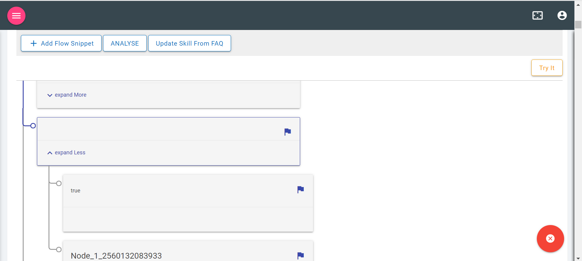
Jump: Each condition can be edited for a jump using the jump button corresponding to the condition to which you want to apply this option. Clicking
on the Jump button displays three conditions: assistant recognize, wait for user input
and response. On selection of the appropriate condition, the use case design console
shows flags on the available nodes on the Landing Node screen. Clicking on any of the
flags attaches that node to the jump.
You can also cancel the jump using the close button on the Landing Node screen.
Delete: Clicking on Delete icon deletes the corresponding condition.
Digressions - Digressions can also be enabled using the same gear icon for context
switching use cases.
Figure 116. Figure 116 – Digressions
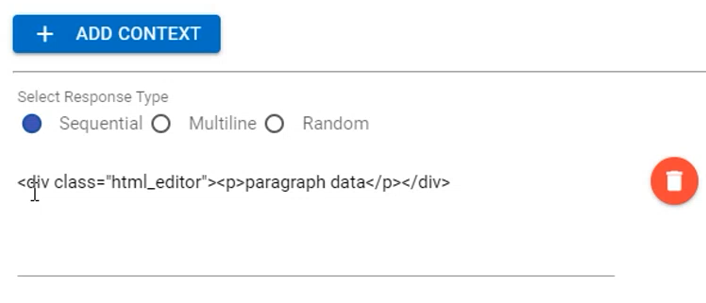
Context variables
Context variables are present in a collapsible and can be added based on
requirement. More variables can be added by using the Add Context button.
Figure 117. Figure 117 – Context Variables
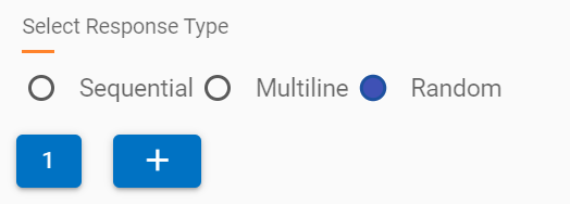
Select Response Type
SME can select the different type of response which is sent by the current node to
the BigFix AEX UI to the end user. The following responses can be configured using the
correct radio button:
Sequential
Multiline
Random
Sequential: Responses are displayed in sequence in the BigFix AEX response in the
same chat block
Multiline: Responses are shown in ordered or unordered sequence in the BigFix AEX
response; however they are in separate chat blocks.
To use multiline, enable the multiline flag as true.
Also use <OL> tag to set sequence of responses
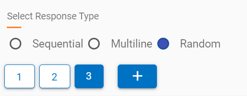
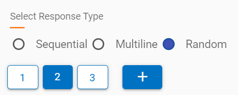
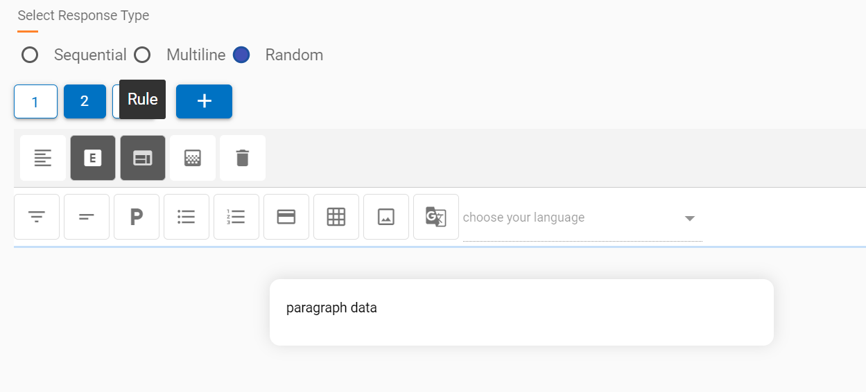
Random: Responses are shown randomly from the list of responses when a node is
executed. Response blocks can be added by using the + icon below the response type
radio button. On adding a new response, the editor changes the focus to the latest
response.
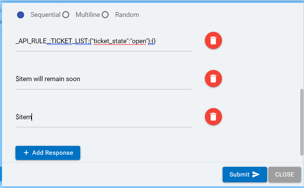
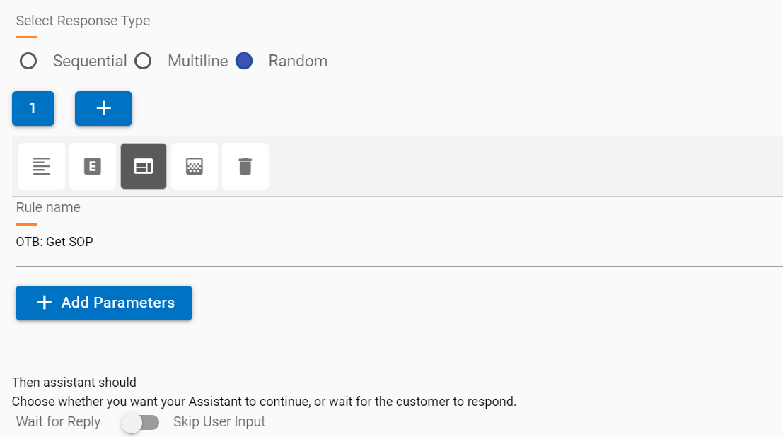
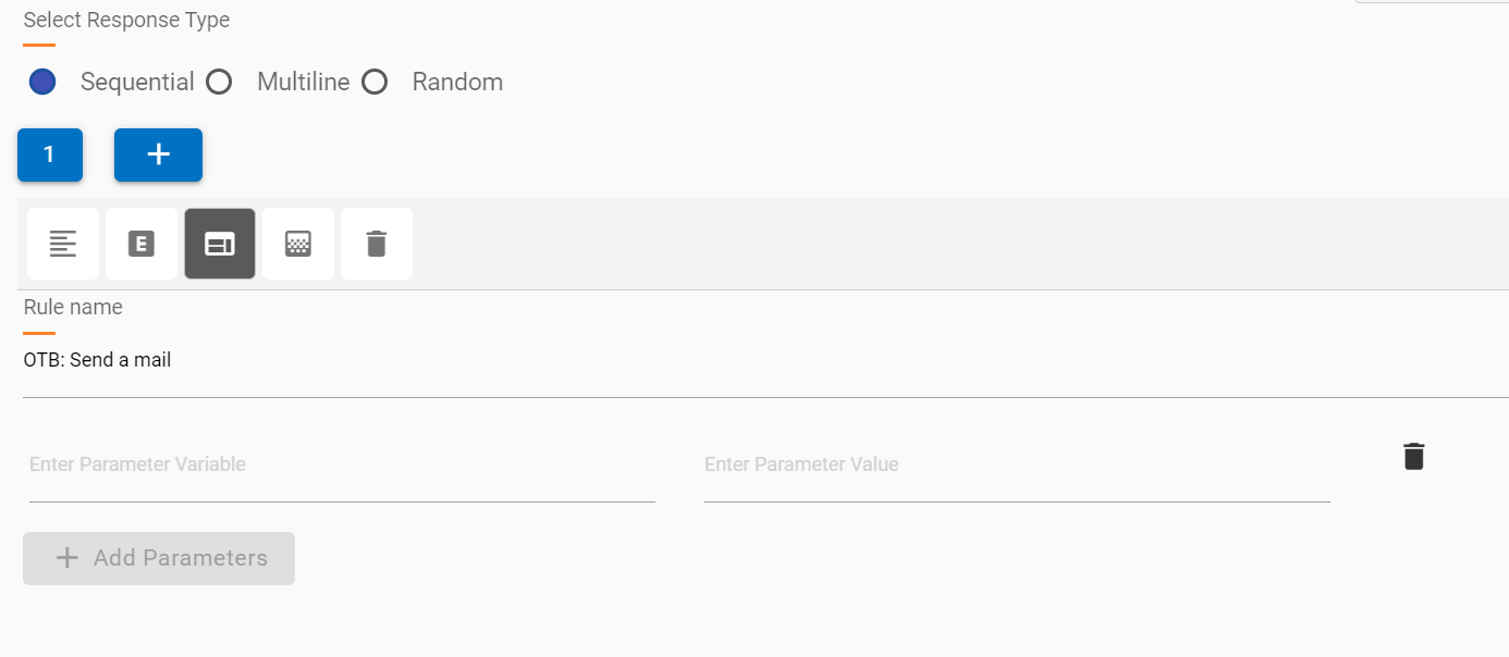
API Rule: API rule provides a simpler way to call Openwhisk functions
or integration actions directly from the use case design editor.
Figure 124. Figure 124 – Rule Selector
The following salient points are relevant:
A drop-down list of existing rules in the current tenants is shown.
An appropriate rule can be selected, and relevant parameters can be passed along with
values.
The added parameters are passed to the selected rule.
Figure 125. Figure 125 – Rule Parameters
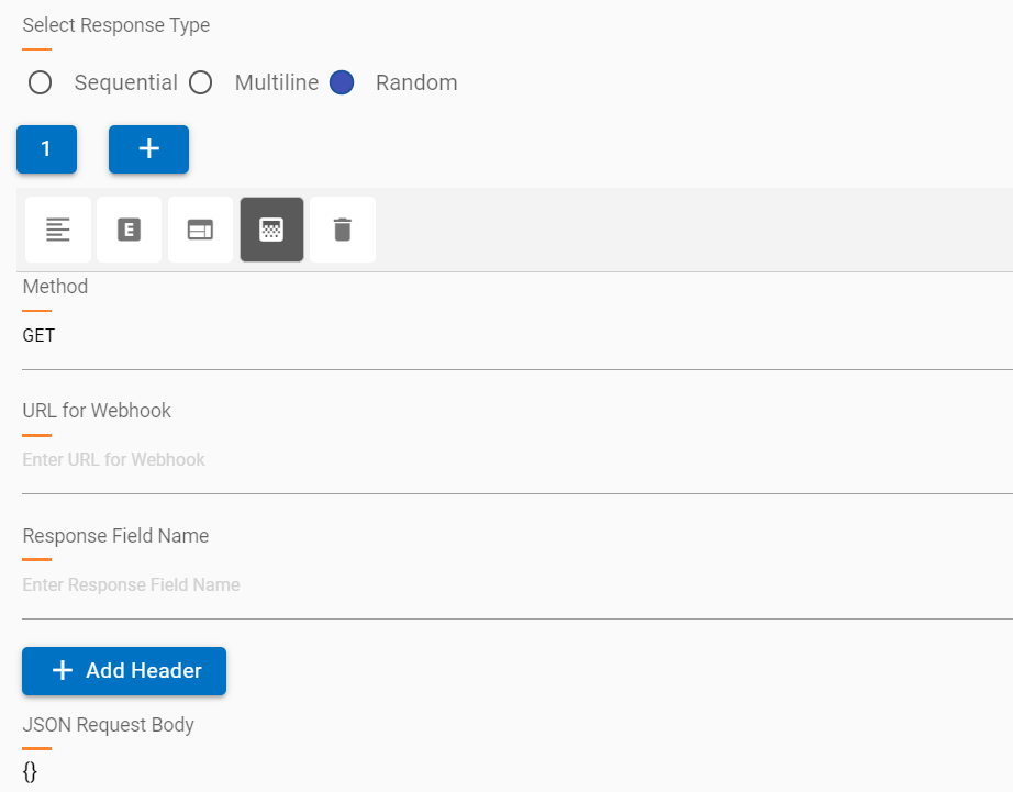
Webhook: Webhooks provide a quick way to call API services with relevant headers
and body parameters to fetch a response.
Multiple webhooks can be added to the same response editor with new responses in the
same node.
Webhook requests can be GET or POST.
Response should be JSON only
Required parameters can be added based on the API service.
It is recommended to check headers and authentication using a service like POSTMAN so
the correct values are passed in the Webhook response.
Figure 126. Figure 126 – Webhook
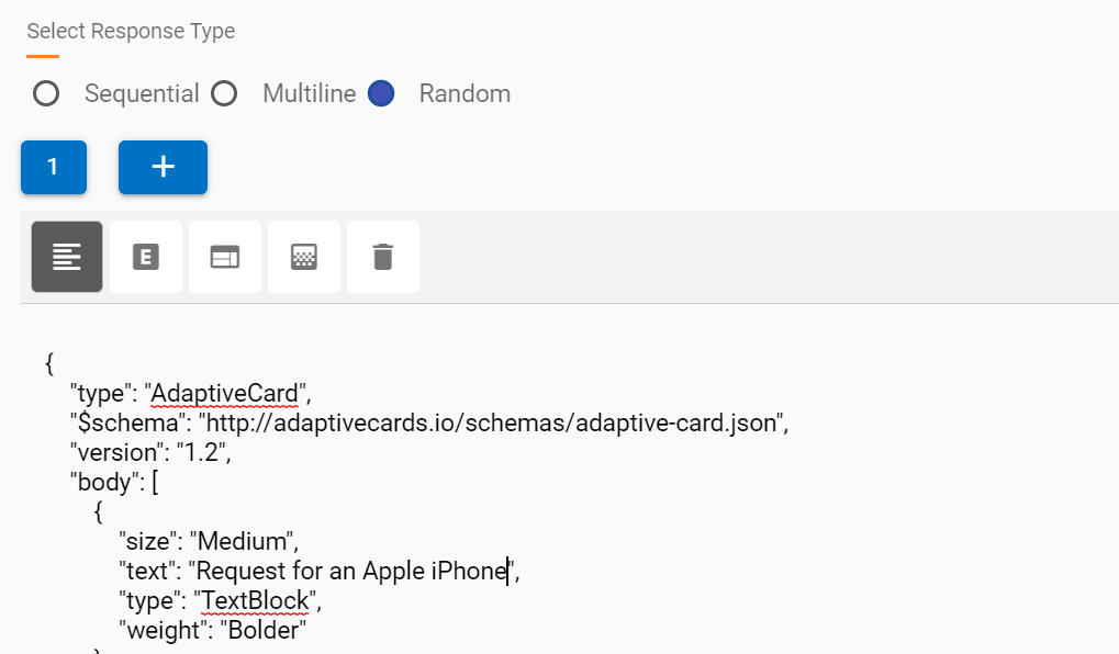
Text and HTML response blocks have a limit of 4096 characters as the response created
in the editor is saved in Watson and sent to the user when a node is executed.
For HTML editor (default type) responses, the 4096 character limit is calculated based
on the raw HTML text, which might have several more characters than the characters
visible in the view.
When the character limit exceeds 4096, the entire editor response is automatically
changed to an SOP and saved, however these technicalities are abstracted from the user
creating the response.
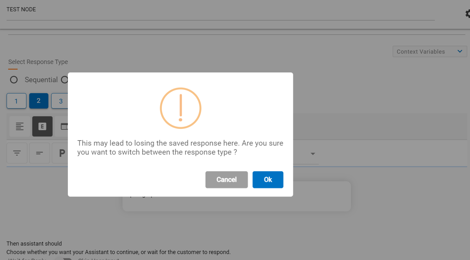
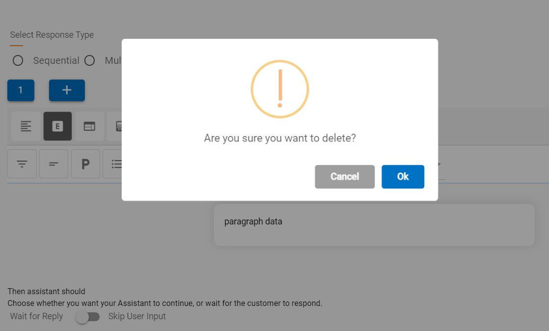
Response Type can be changed to other types as well, but the change will delete all
the data from the current type, and you will encounter a warning before making the
change.
Figure 127. Figure 127 – Changing Response Type from Editor to RuleFigure 128. Figure 128 – Changing Response Type Warning
A response block can also be deleted using the delete button . This action deletes the current block on focus and returns focus to the previous
block. If there is only one response and that it deleted, a new first block is auto
added.
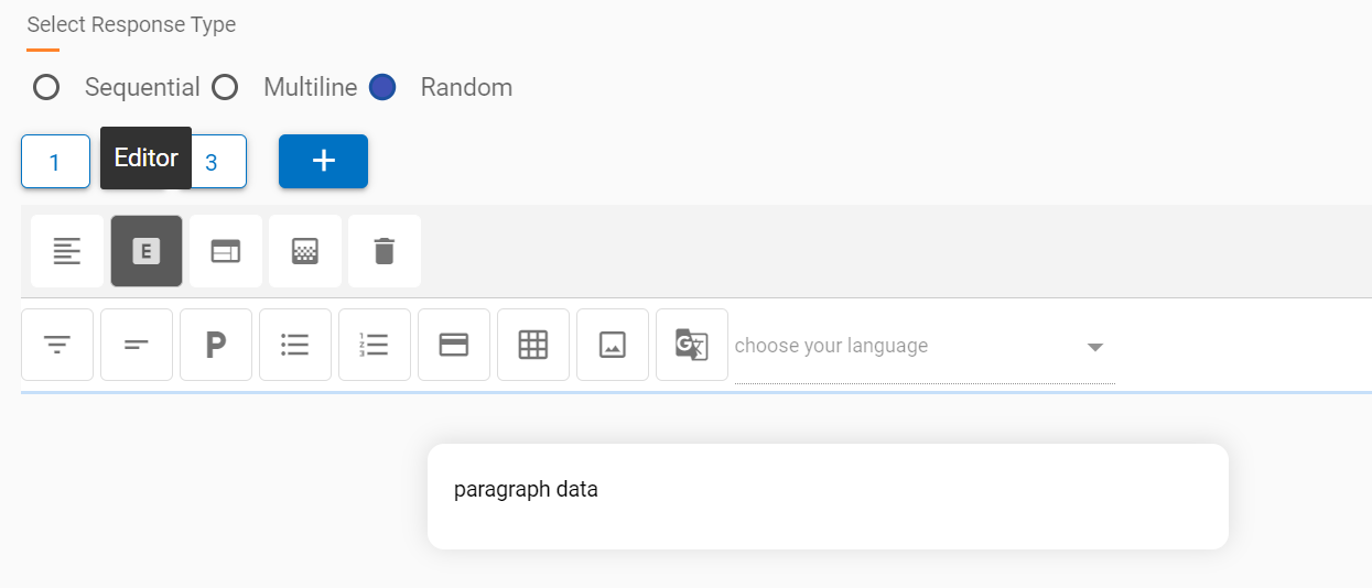
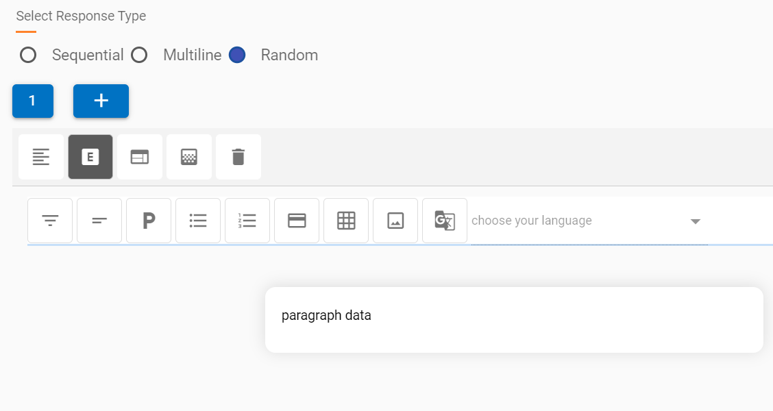
The following pointers outline the basic capabilities of the default HTML
editor response type.
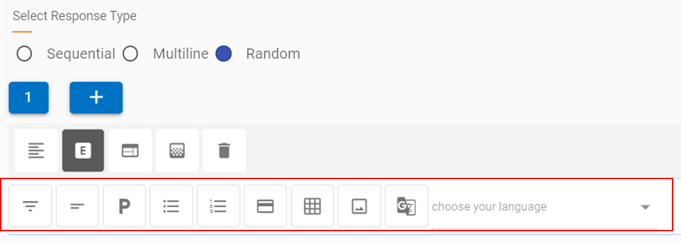
The editor contains a components bar which can be added to the response based on the
requirement.
Figure 131. Figure 131 – HTML Editor Components
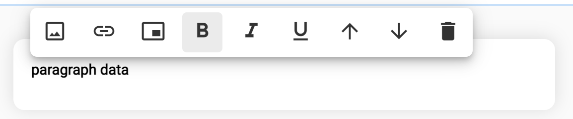
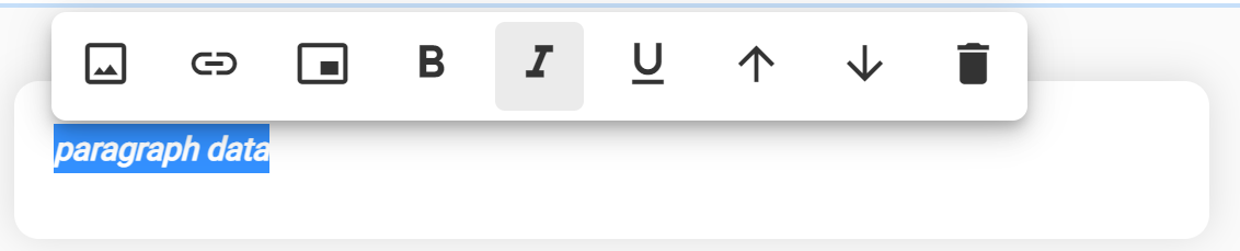
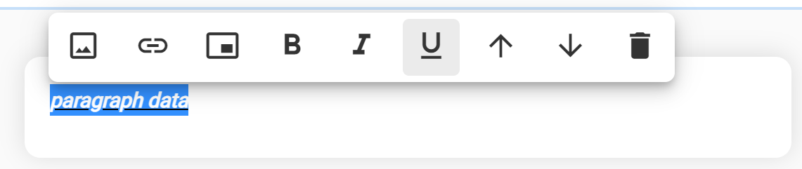
The buttons represent basic HTML pre-built components, which in the background add the
requisite HTML code. This allows the response creator or the cognitive SME to focus on
the user experience and doesn’t require knowledge of HTML scripting.
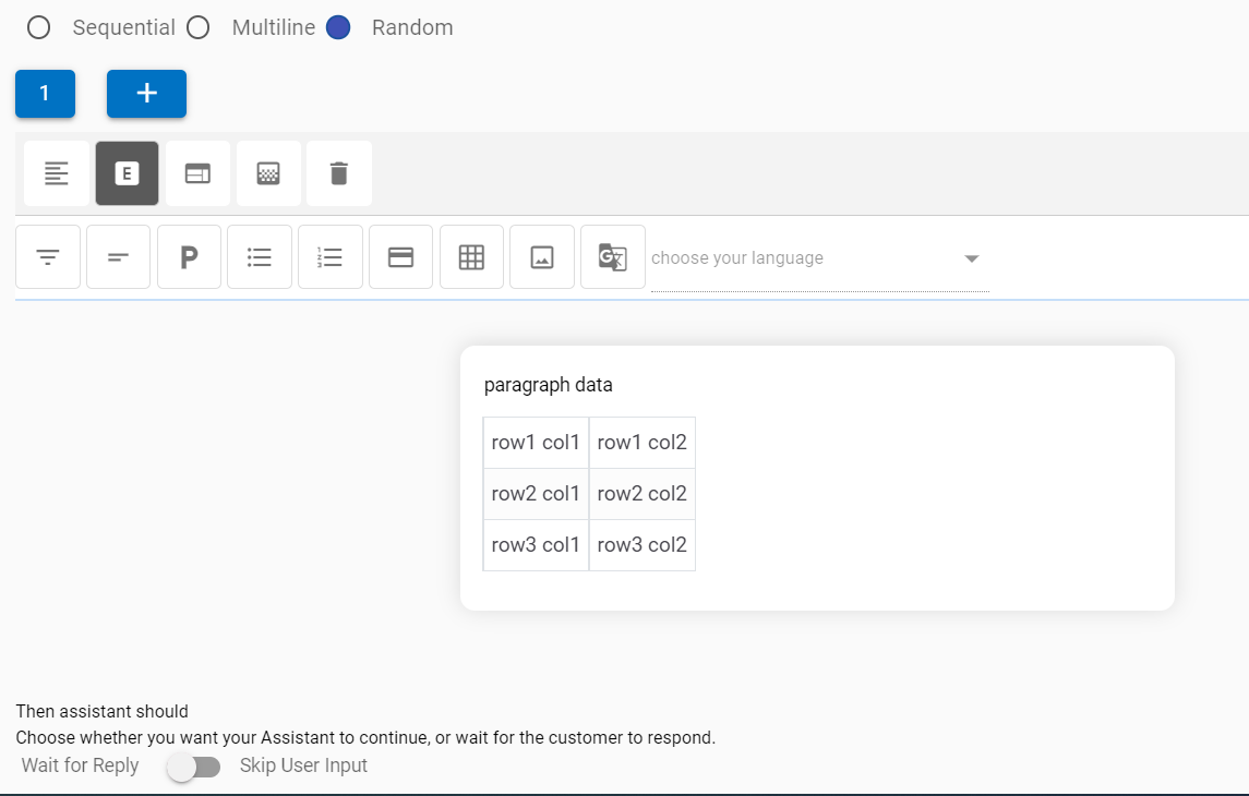
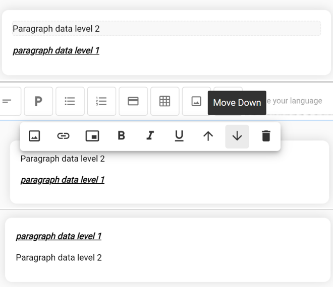
The components when clicked, are added to the response section, as shown in the
example below, where a table is added below a paragraph section.
Editor components are self-explanatory; these components are listed as follows in the
same order as in the screenshot above:
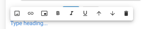
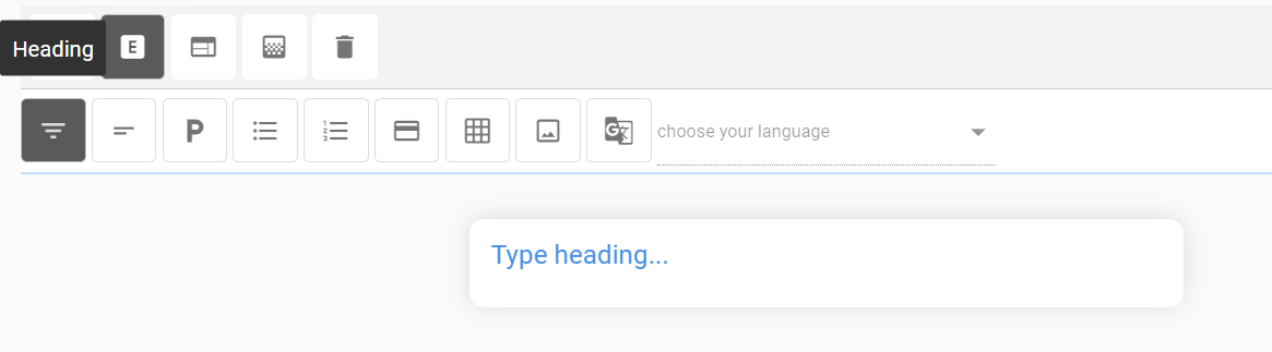
Heading
Figure 133. Figure 133 – Heading Component
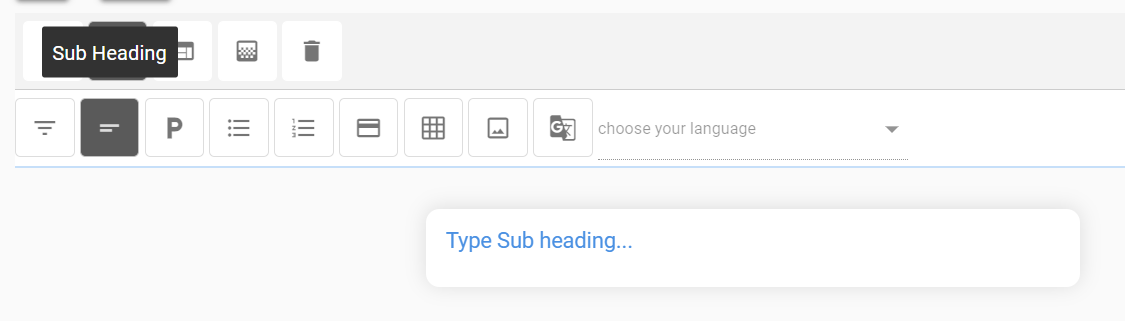
Subheading
Figure 134. Figure 134 – Subheading Component
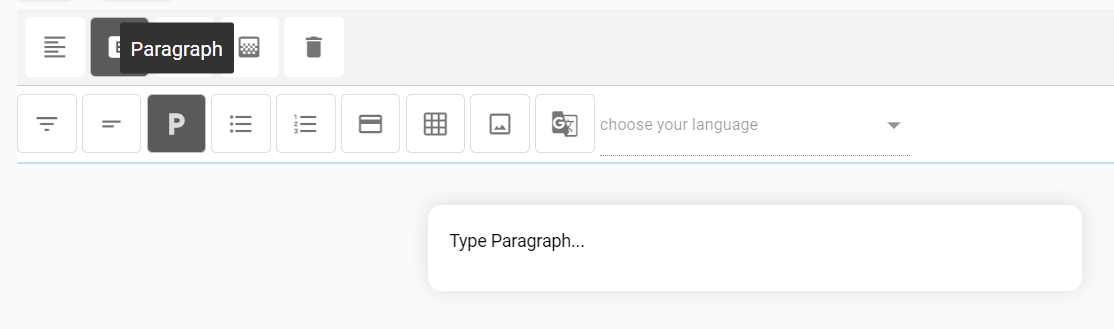
Paragraph
Figure 135. Figure 135 – Paragraph Component
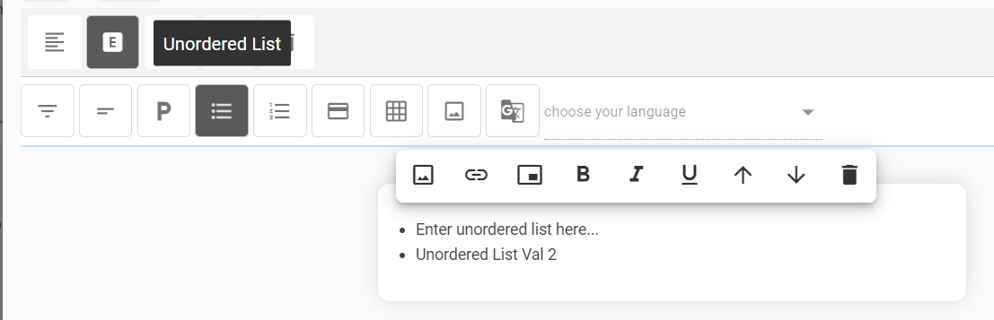
Unordered list
Figure 136. Figure 136 – Unordered Component
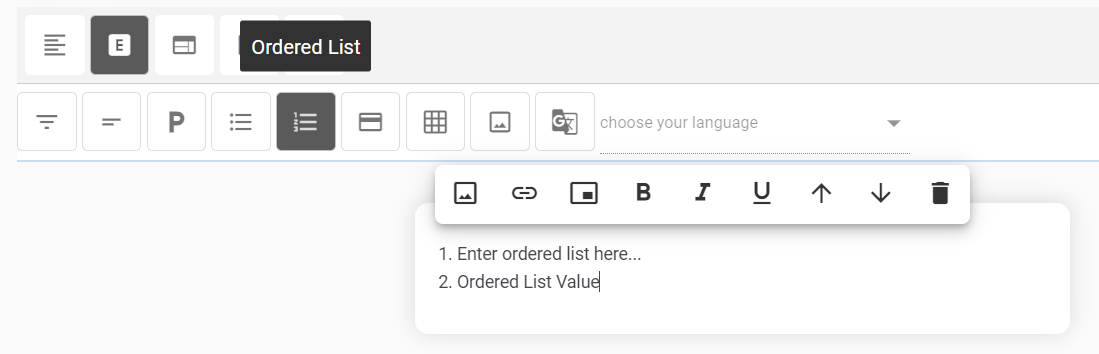
Ordered list
Figure 137. Figure 137 – Ordered Component
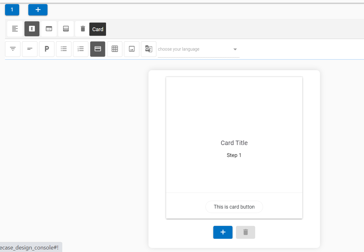
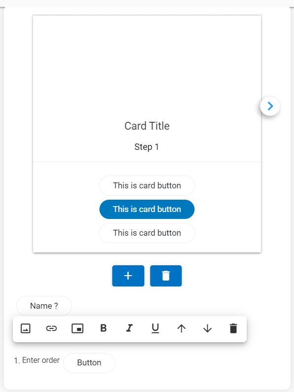
Card: The Card component provides a pre-built HTML component that contains a title, body,
and a button bar.
Figure 138. Figure 138 – Custom
Card Component
More cards can be added to a carousel by clicking the button. This adds cards in a sequence,
next to the current card. The focus also changes to the latest card
in the carousel.
With the addition of new cards, navigation icons are also added
to the UI to move between the cards.
Any card can be deleted by using the delete icon at the bottom of the card.
Figure 139. Figure 139 –
Addition/Deletion of Cards
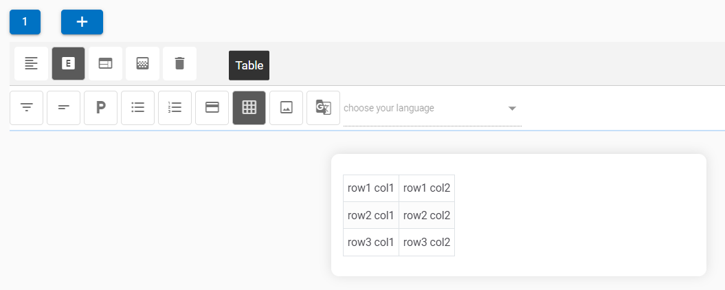
Table
Figure 140. Figure 140 – Table
Component
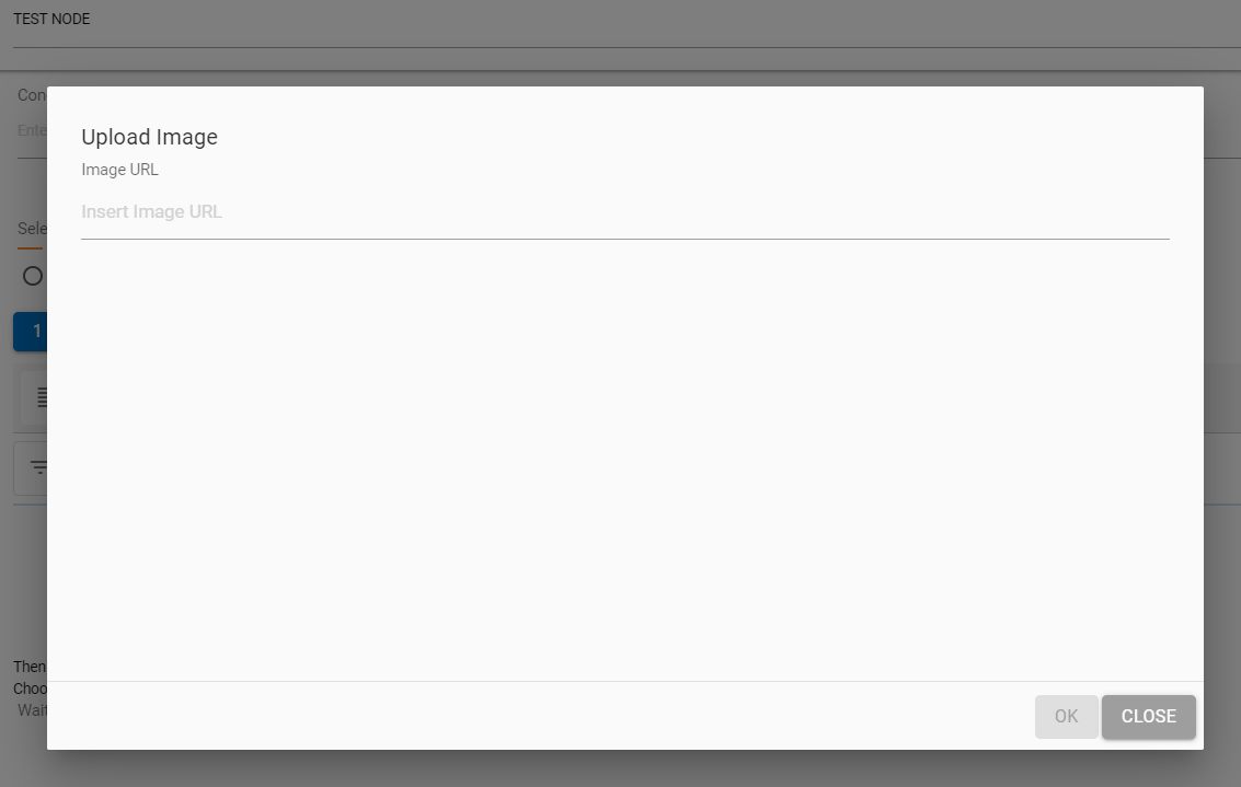
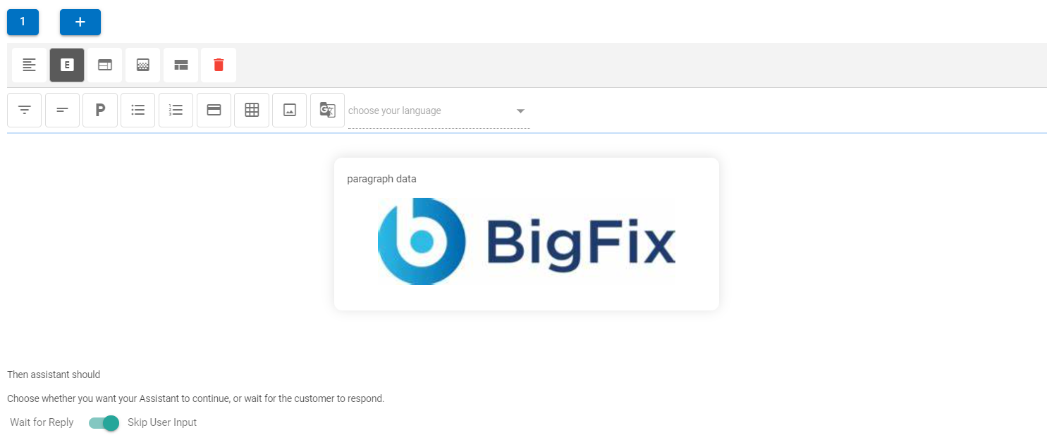
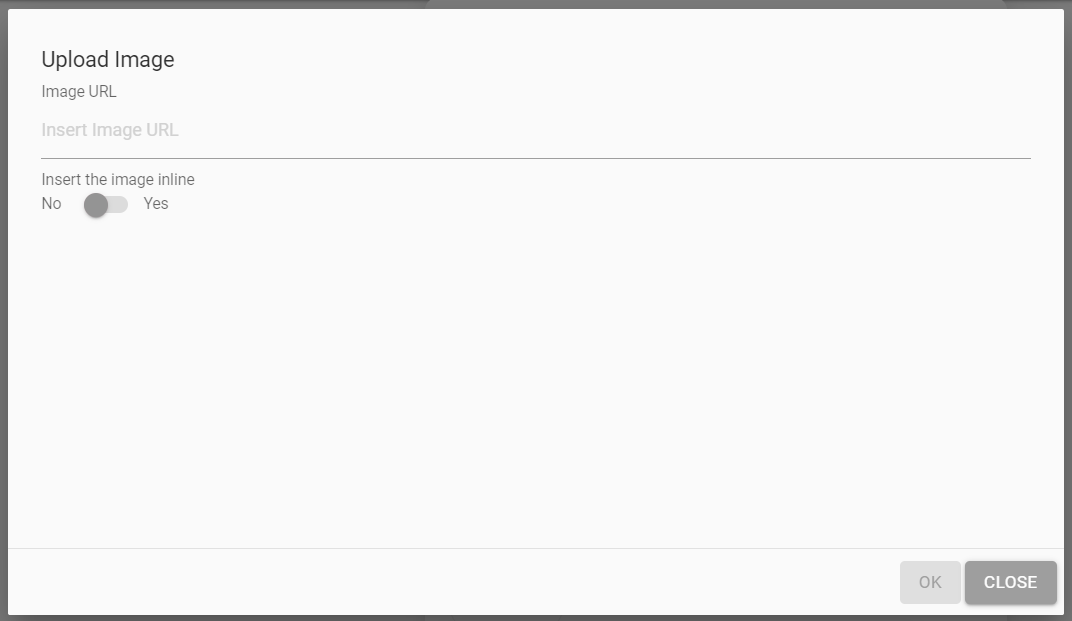
Image
When a user clicks on the Image component, a dialog box appears
where a public image URL must be provided for the image to be
displayed in the image card.
On providing the right URL, the picture would be rendered
inside the image panel.
Figure 142. Figure 142 – Image
Component
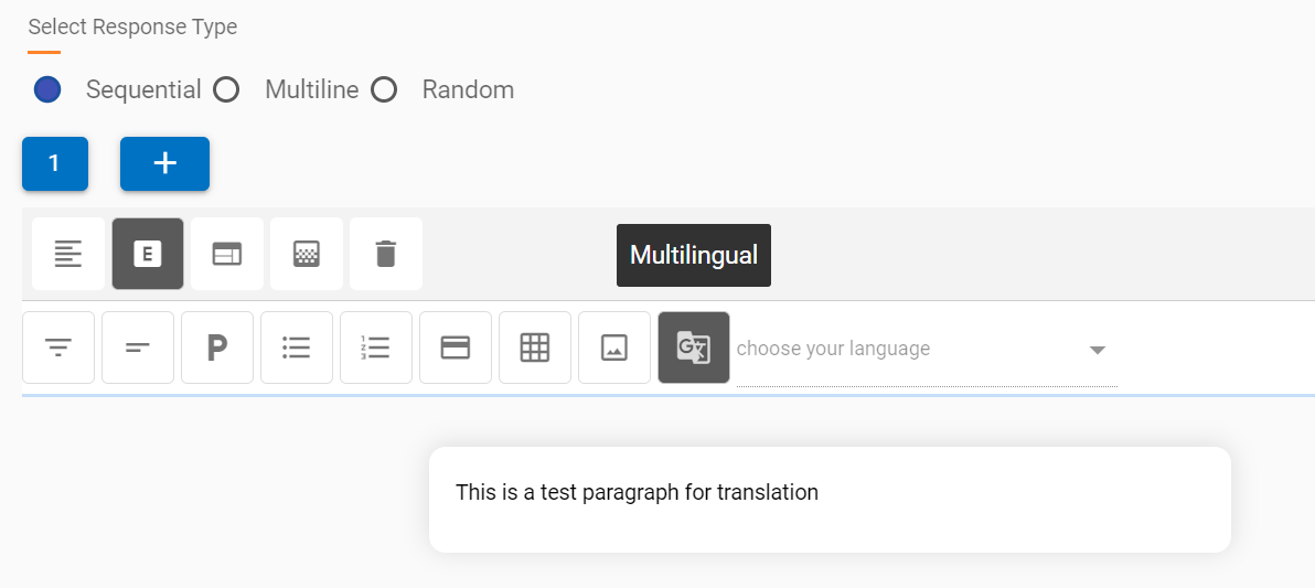
Translation
This option uses BigFix AEX’s fast translation
capabilities to translate text in over 51 languages at once, right
from the use case design console’s HTML editor.
Multilingual connector for the current tenant must be activated
before use of this feature.
This functionality can be used only once for
the current set of text. If the text needs to be changed, the
current node needs to be deleted and re-created for the translation
to be triggered again.
This is not the most ideal functionality for translation (since
automated translation always has lower accuracy than manual),
however for quick use case implementation in different languages
this capability should be used, language should always be validated
by a language SME.
Not all 51 languages are available on the chat console.
However, they are currently being converted and saved as a
knowledge repository in the backend.
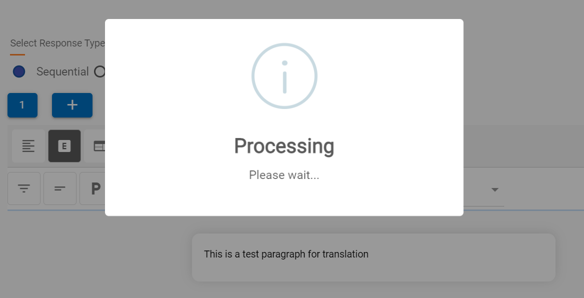
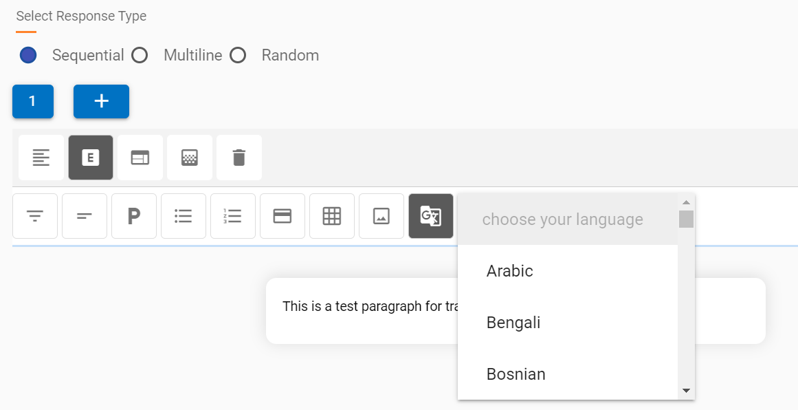
To use this functionality, after a response block is suitable
for translation, the user needs to click on the translate component
button and wait for the window to confirm the translation is done.
In the following image, the translation component is translating
the statement “This is a test paragraph for
translation.”
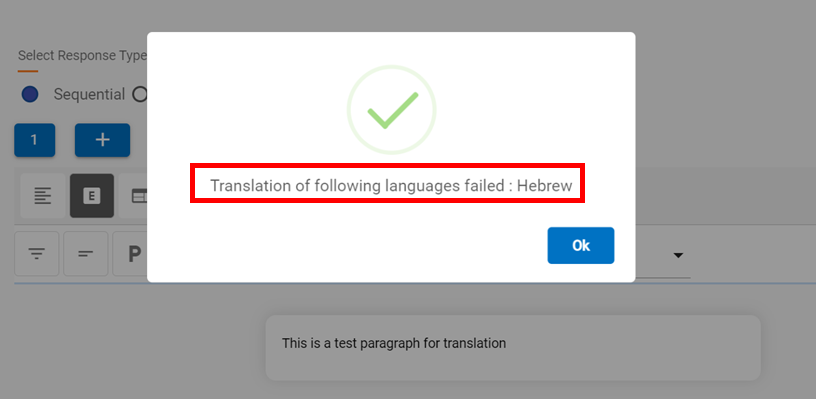
Once the translation is complete, you will see the following
dialog box confirm the translation of all 51 languages, except any
failures, which are also listed.
Translation of all successful languages can be accessed using
the drop-down which is populated post translation, like in the
following screenshot:
Figure 146. Figure 146 –
Translation Component – Successful Languages
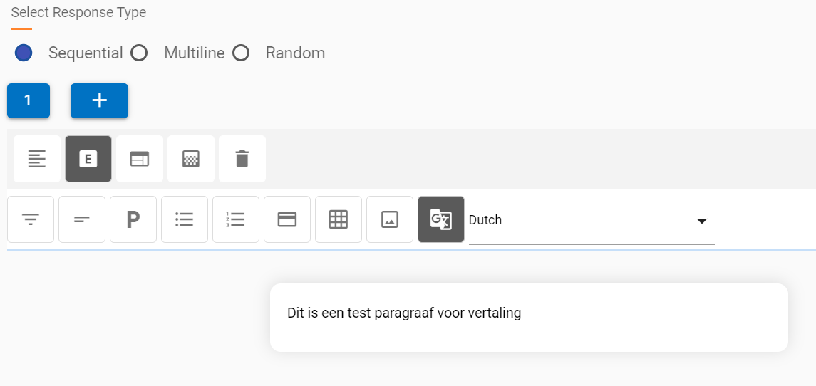
On clicking the required language, the translation appears in
the same response block. We have selected Dutch from the drop-down
in this example for our original text.
Figure 147. Figure 147 –
Translation Component – Translation in selected
language
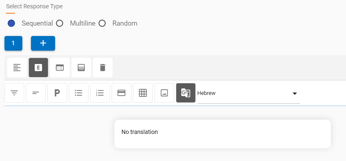
The response for failed languages will be a default “No
translation” when selected from the drop-down. For example,
the failed translation into the Hebrew language.
Figure 148. Figure 148 – HTML
Editor Component Addition
Component Properties
Each component, when added to the response, shows options which
are applicable to it on click, a list of all these
options is as the following (they will change based
on every component):
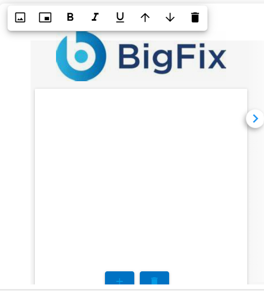
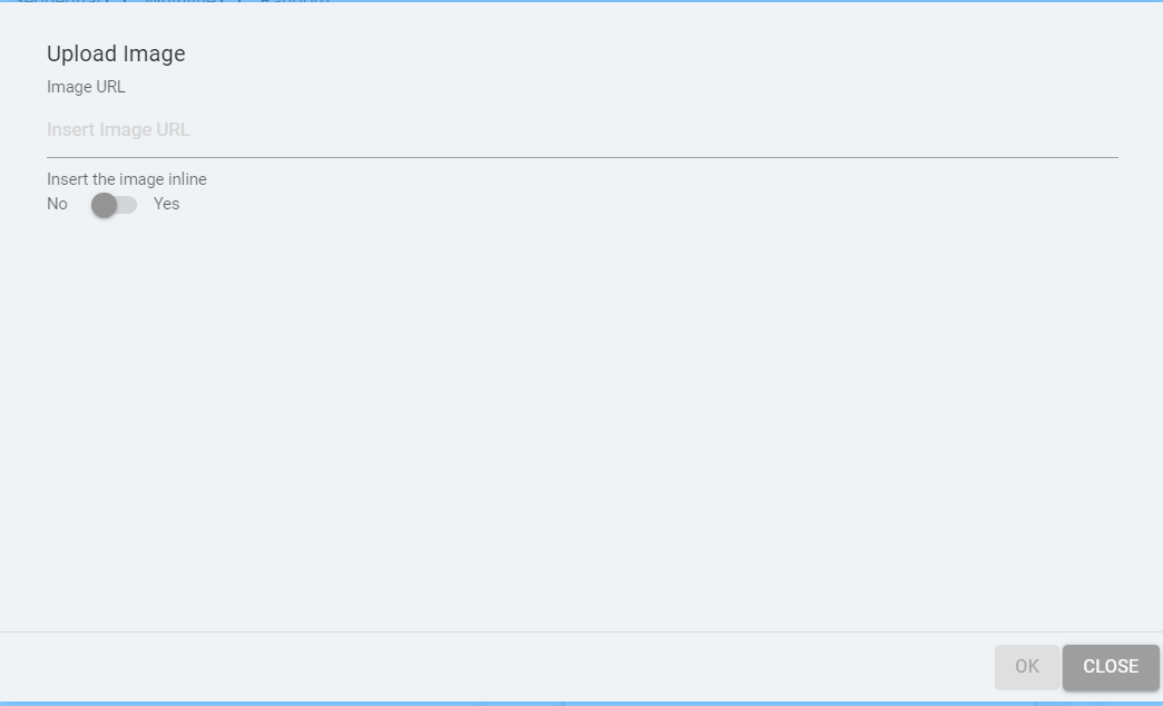
Insert Image:
This option adds an image inline or as a new block. Insert an
image inline based on the component.
For cards, images are always inserted inside the body of the
card, above the card title, the Upload Image dialog box does not
show an inline option.
 corresponding to the skill to
be deleted.
corresponding to the skill to
be deleted.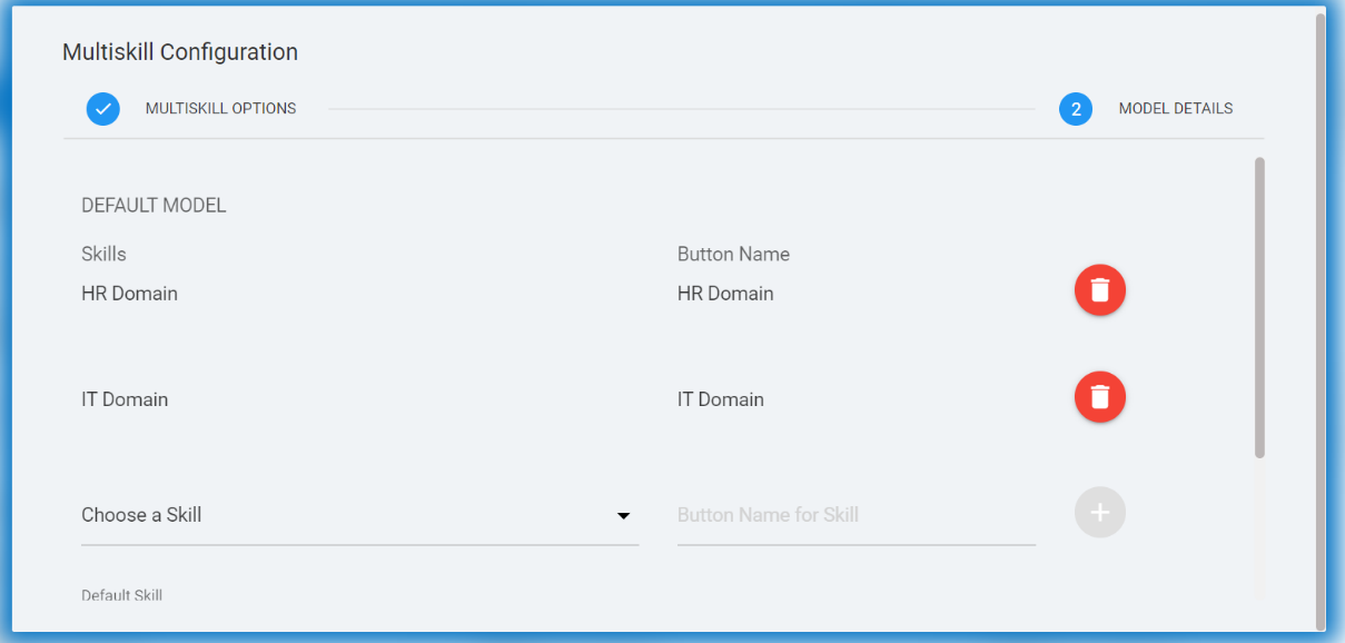
 and to move a skill down, click the Move
down arrow
and to move a skill down, click the Move
down arrow  .
.
.png)
.png)
.png) corresponding to the skill
to be deleted.
corresponding to the skill
to be deleted..png)
.png)
.png) corresponding to the skill
to be deleted.
corresponding to the skill
to be deleted.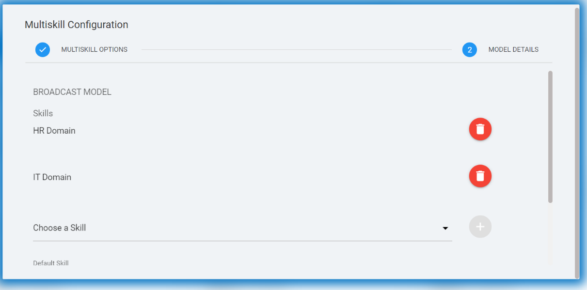
.png)
.png)
.png) corresponding to the skill to be
deleted.
corresponding to the skill to be
deleted.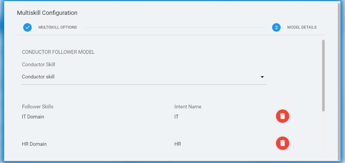
 corresponding to the intent that you want
to delete.
corresponding to the intent that you want
to delete.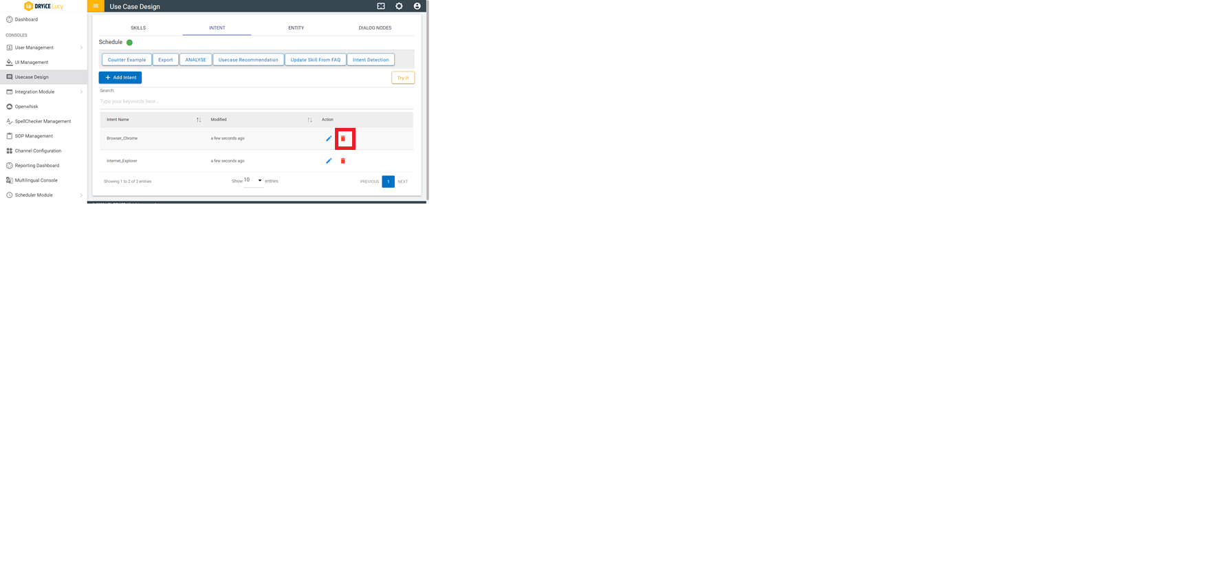
 corresponding to the variation.
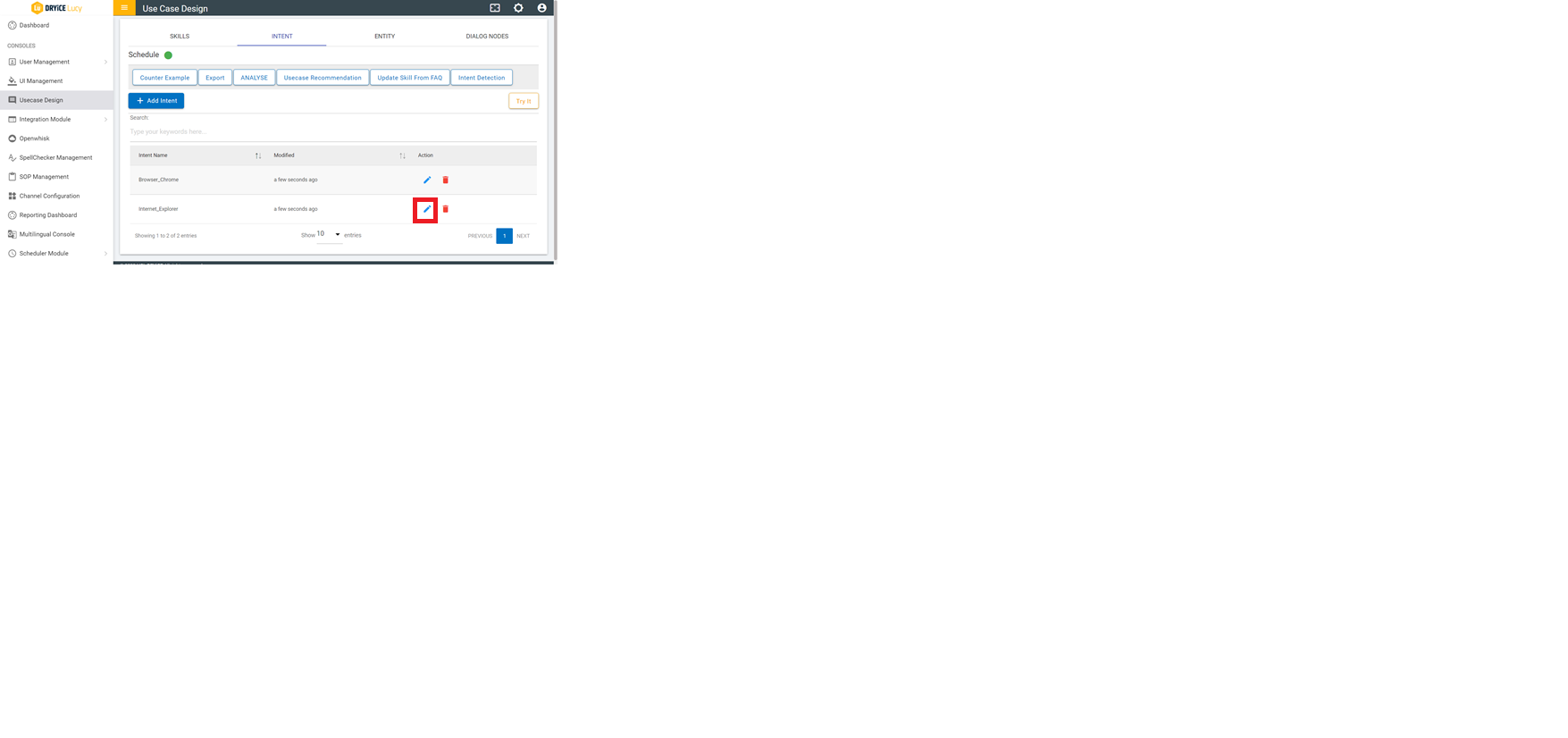
.png) to delete the corresponding
entity.
to delete the corresponding
entity.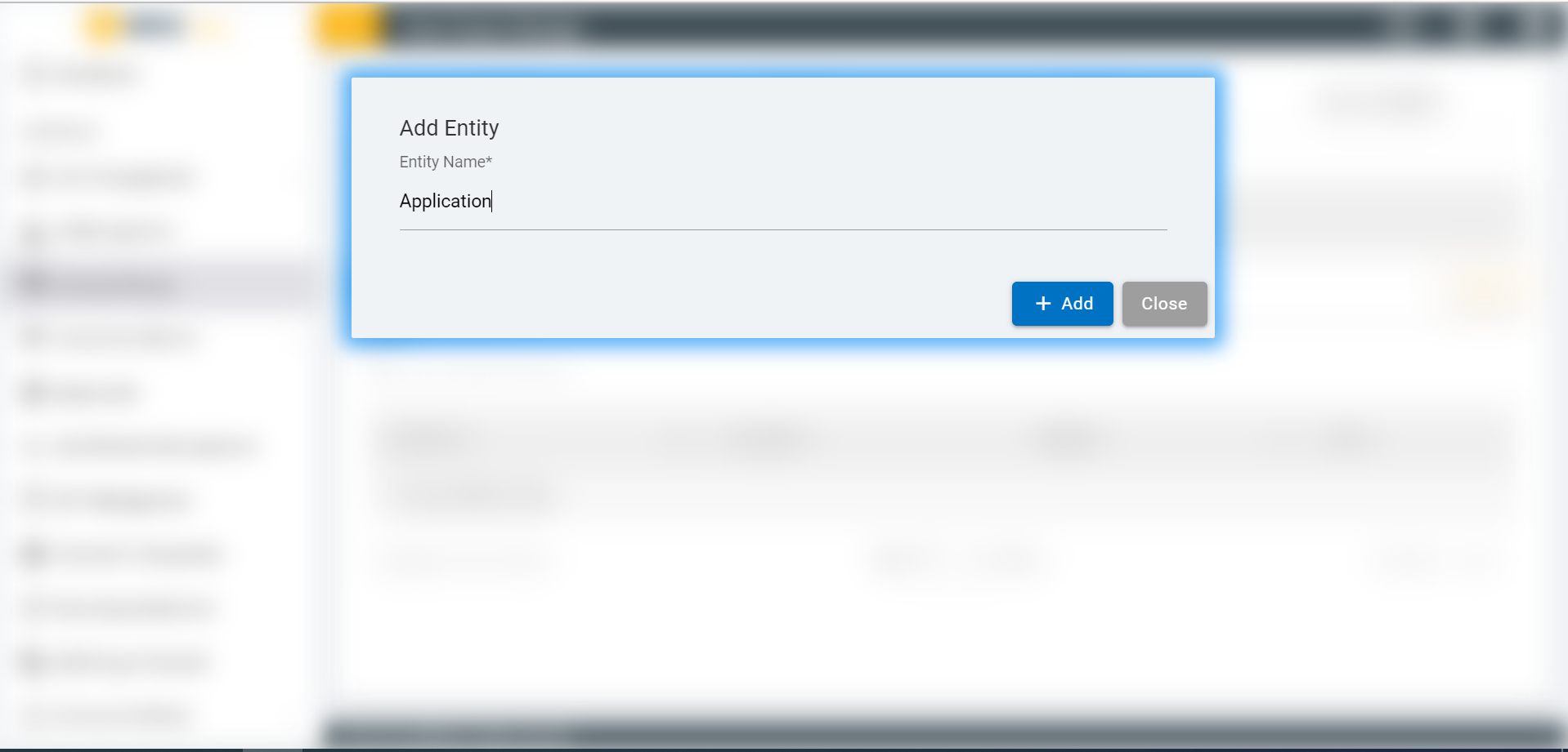

.png) corresponding to the entity value
that you want to delete.
corresponding to the entity value
that you want to delete.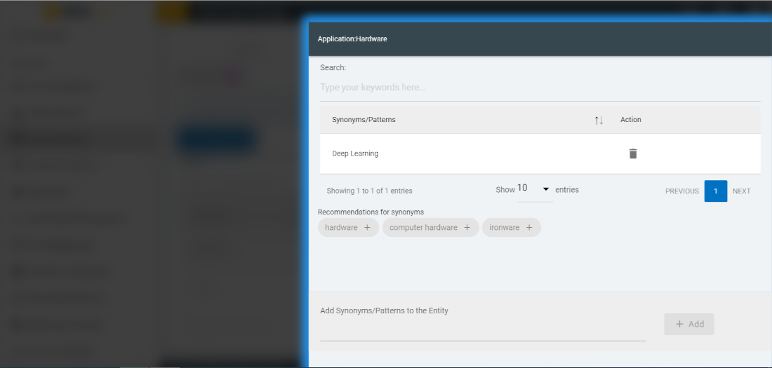
.png) corresponding the synonym that you
want to delete.
corresponding the synonym that you
want to delete.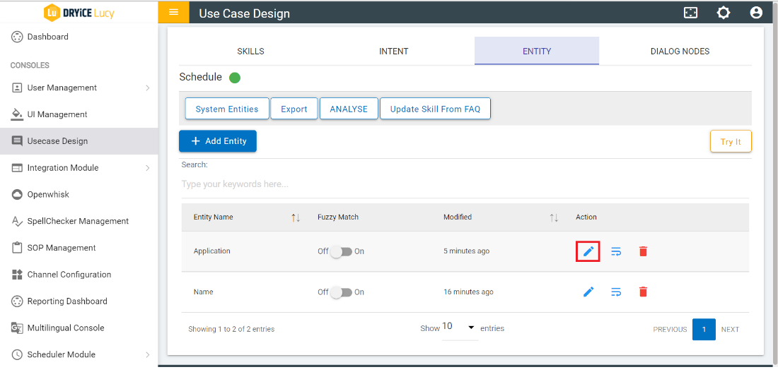
 )
)
 to
check the settings of form. The following screen appears:
to
check the settings of form. The following screen appears: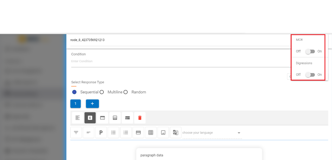

 to open the dialog node that was
triggered by your input.
to open the dialog node that was
triggered by your input.
 opens the list where it
shows all the intents and the confidence score of the intent for the input query.
opens the list where it
shows all the intents and the confidence score of the intent for the input query.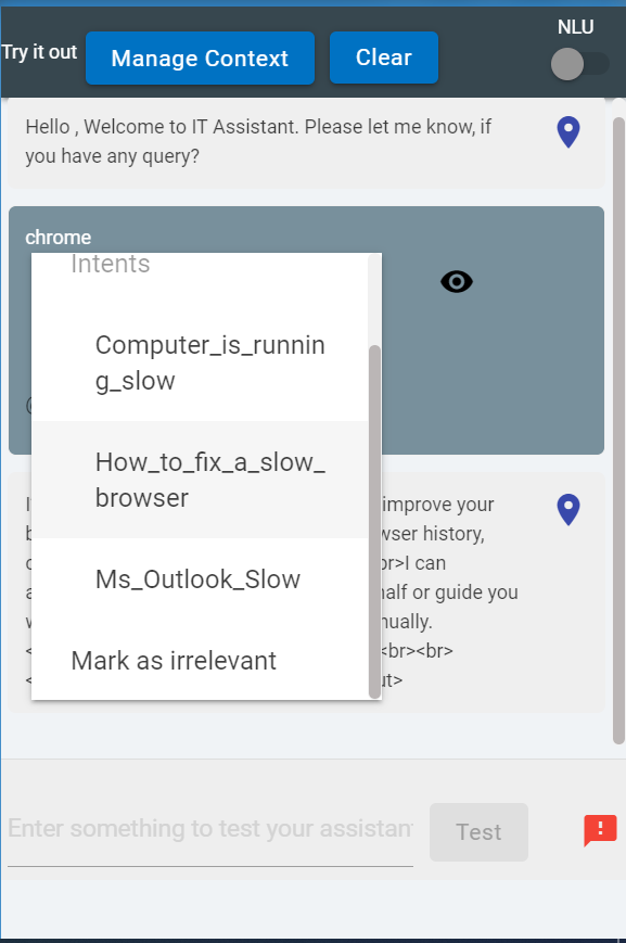
 )
)
.png) on the right side of the node title displays the following options:
on the right side of the node title displays the following options: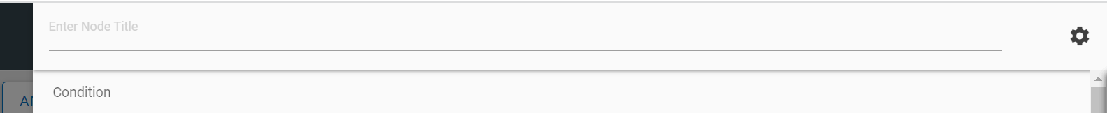
 corresponding to the node that you want to move.
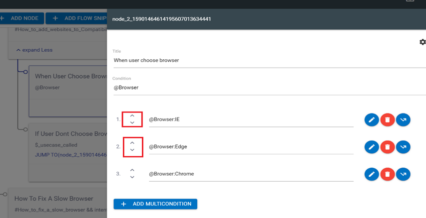
 corresponding to the condition to be edited. You can edit the condition to
provide a response and context variables.
corresponding to the condition to be edited. You can edit the condition to
provide a response and context variables.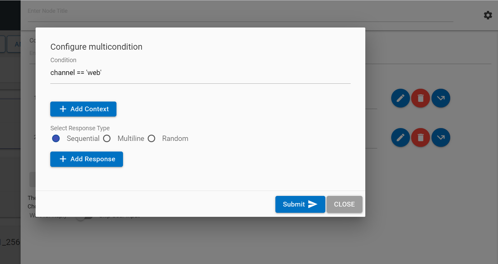
 corresponding to the condition to which you want to apply this option. Clicking
on the Jump button displays three conditions: assistant recognize, wait for user input
and response. On selection of the appropriate condition, the use case design console
shows flags on the available nodes on the Landing Node screen. Clicking on any of the
flags attaches that node to the jump.
corresponding to the condition to which you want to apply this option. Clicking
on the Jump button displays three conditions: assistant recognize, wait for user input
and response. On selection of the appropriate condition, the use case design console
shows flags on the available nodes on the Landing Node screen. Clicking on any of the
flags attaches that node to the jump.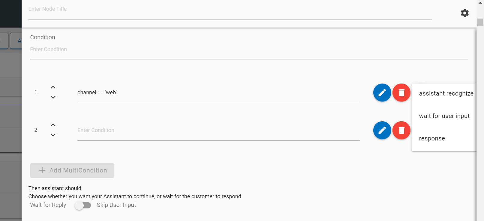
 on the Landing Node screen.
 deletes the corresponding condition.
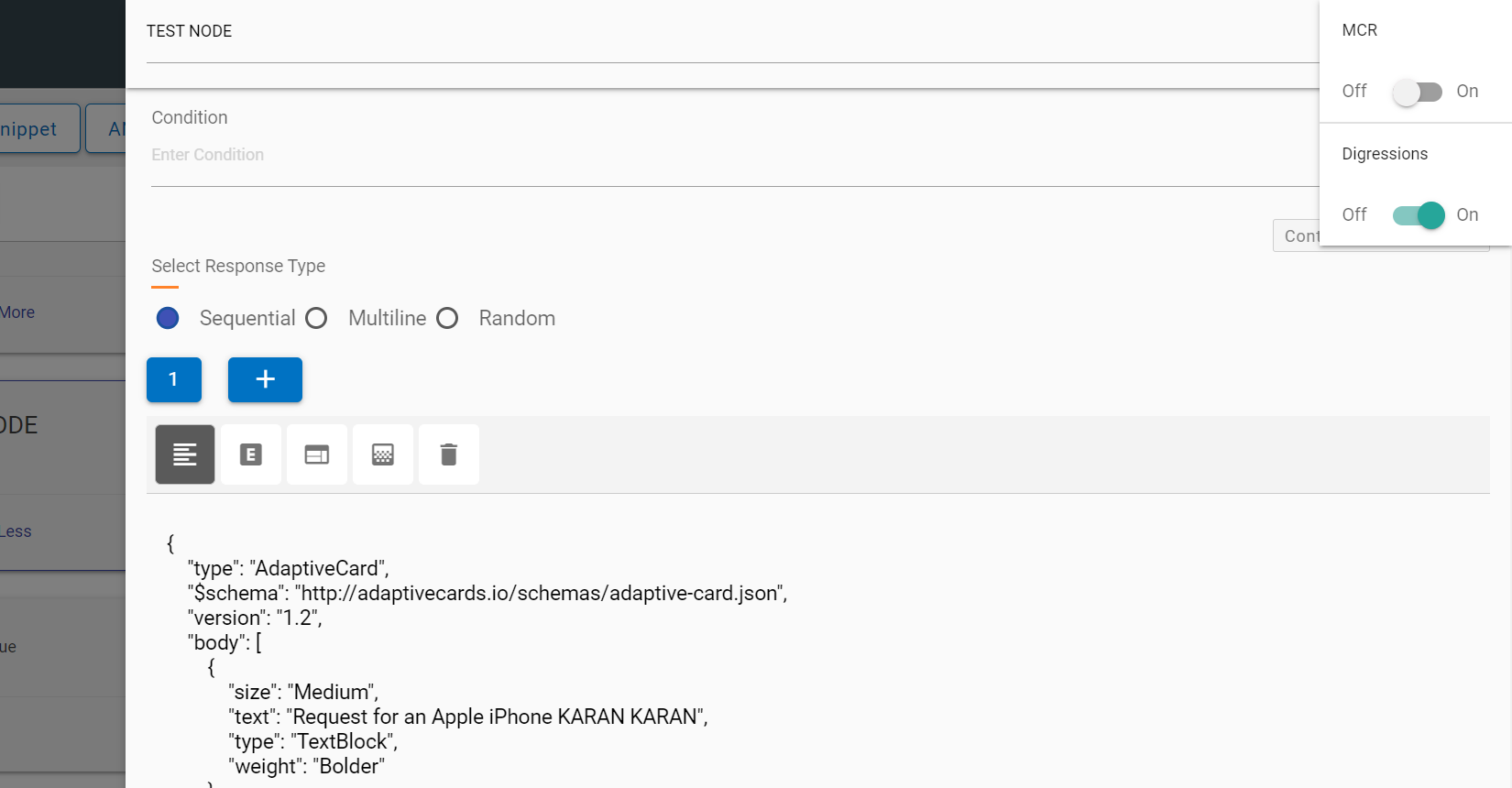
 . This action deletes the current block on focus and returns focus to the previous
block. If there is only one response and that it deleted, a new first block is auto
added.
. This action deletes the current block on focus and returns focus to the previous
block. If there is only one response and that it deleted, a new first block is auto
added.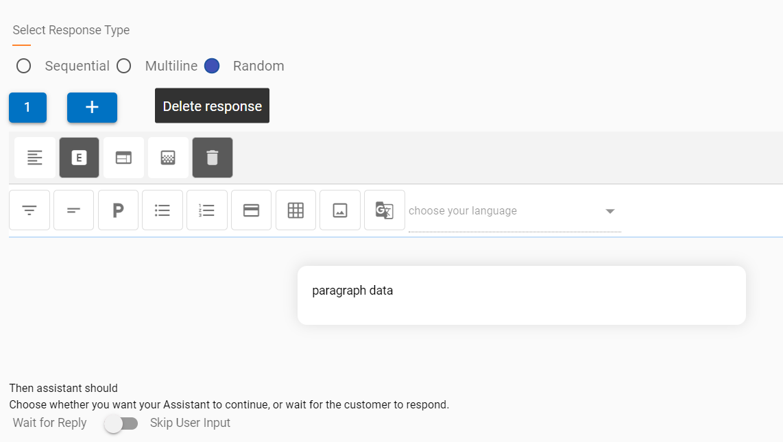
 button. This adds cards in a sequence,
next to the current card. The focus also changes to the latest card
in the carousel.
button. This adds cards in a sequence,
next to the current card. The focus also changes to the latest card
in the carousel. at the bottom of the card.
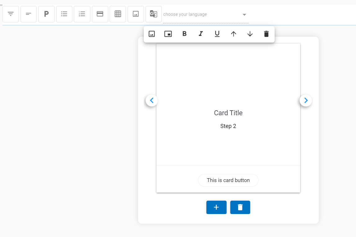


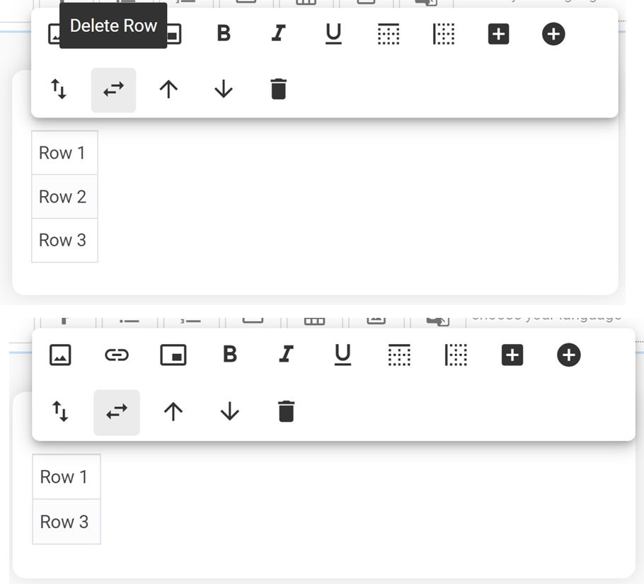
 (Available only in the Table
Component)
(Available only in the Table
Component)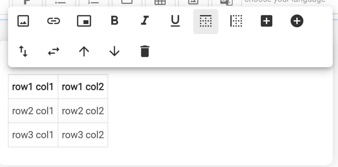
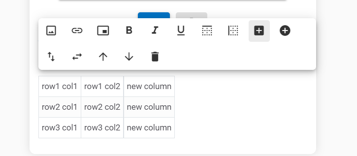
 (Available only in Table Component)
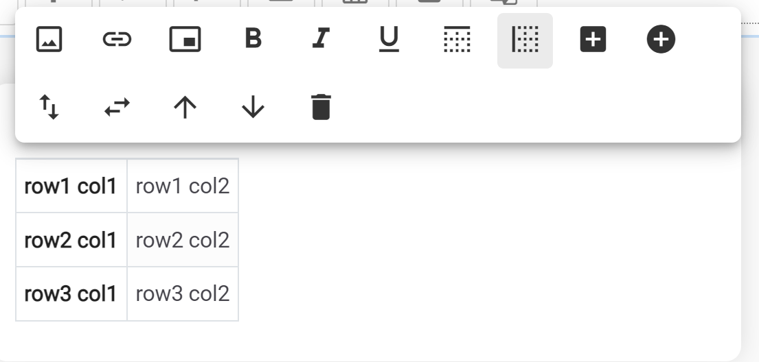
 (Available only in Table
Component)
(Available only in Table
Component)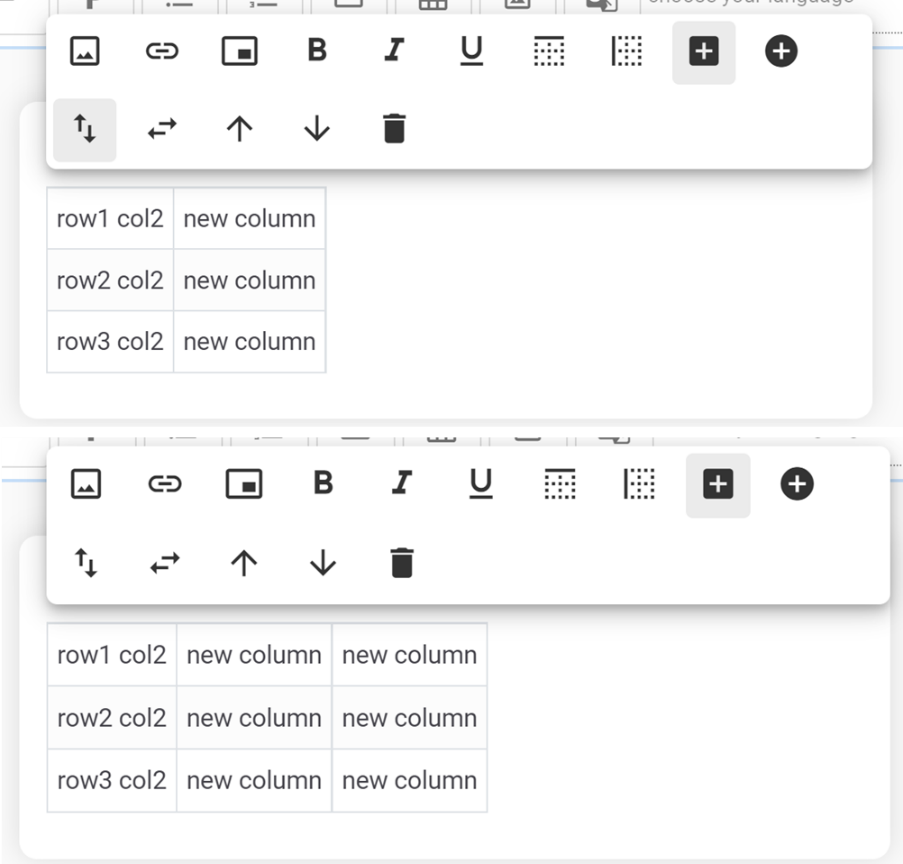
 (Available only in Table
Component)
(Available only in Table
Component)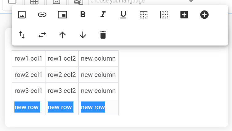
 (Available only in Table
Component)
(Available only in Table
Component)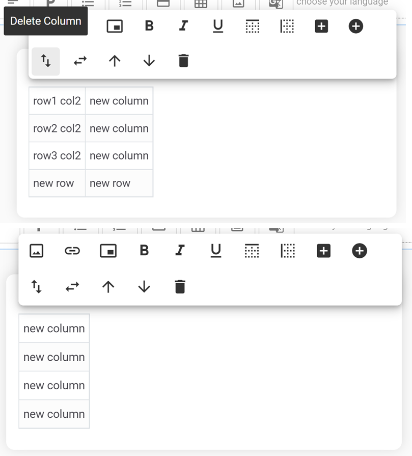
 (Available only in Table Component)